
Low-abrasion windproof sealing-tape machine

A belt conveyor, low-wear technology, used in conveyors, conveyor objects, transportation and packaging, etc., can solve the problems of belt deviation, belt breakage, delay in transportation work, etc., to extend the belt and rollers, and prevent waste of resources. , the effect of prolonging the service life

Active Publication Date: 2015-03-25
ANHUI HUAYI PACKAGING CO LTD
View PDF6 Cites 0 Cited by
  • Summary
  • Abstract
  • Description
  • Claims
  • Application Information

AI Technical Summary

Problems solved by technology

Since the existing belt conveyors usually only have rollers, it is found that when the material falls from a high place, it is easy to damage the belt of the conveyor, and the belt is easy to break from between the two rollers. Once the belt is broken, it will be repaired It is very cumbersome and will delay the transportation work
Existing belt conveyors are seldom equipped with shock-absorbing devices, and it is easy to have the problem of belt deviation
[0003] Due to the large contact area between the idler and the belt of the existing conveyor, both the belt and the idler have the problem of rapid wear and tear, and the idler needs to be replaced frequently, resulting in high maintenance costs
[0004] In addition, the tape machine is mostly installed in the open air. When the wind blows, the materials on the tape machine are easily blown off by the wind, which affects the normal transportation of materials.

Method used


Image

  • Low-abrasion windproof sealing-tape machine
  • Low-abrasion windproof sealing-tape machine

Examples


Embodiment 1

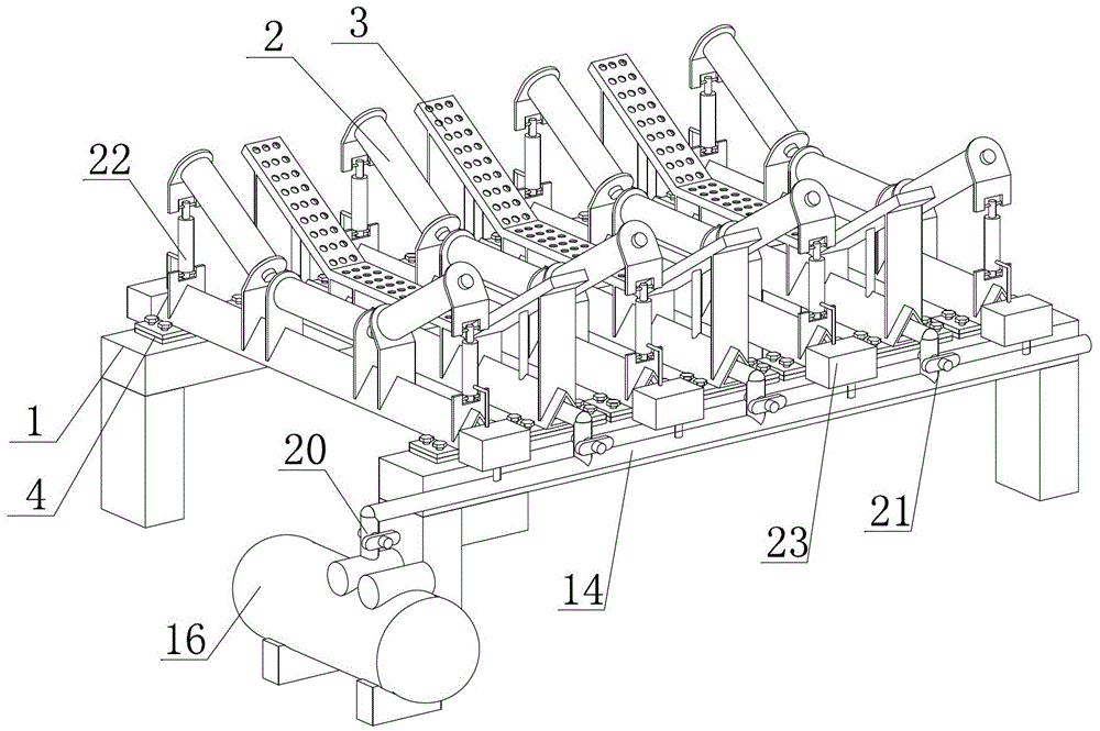
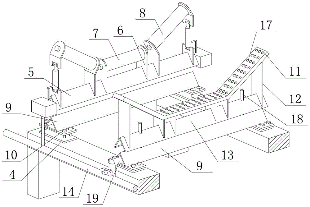
[0019] Embodiment 1 of the present invention: as figure 1 As shown in the figure, a low-wear windproof tape machine includes a roller group bracket 1 and a grooved roller group 2. The grooved roller group 2 is evenly distributed on the roller group bracket 1, and any two adjacent grooved rollers There is a group of air jet pallets 3 between the groups 2; the bottom of the trough roller group 2 and the air jet pallet 3 is equipped with a shock absorber 4; one side of the roller bracket 1 is provided with a general gas delivery pipe Road 14, each air jet pallet group 3 is connected with the total gas delivery pipeline 14, and the total gas delivery pipeline 14 is connected with the air pump 16; each trough idler group 2 is provided with a cylinder 22, the said The cylinder 22 is connected with the main gas delivery pipeline 14 through an electric valve 23 . A valve A20 is provided at the connecting end of the total gas delivery pipeline 14 and the air pump 16; each branch air p...

Embodiment 2

[0023] Embodiment 2 of the present invention: as figure 1 As shown in the figure, a low-wear windproof tape machine includes a roller group bracket 1 and a grooved roller group 2. The grooved roller group 2 is evenly distributed on the roller group bracket 1, and any two adjacent grooved rollers There is a group of air jet pallets 3 between the groups 2; the bottom of the trough roller group 2 and the air jet pallet 3 is equipped with a shock absorber 4; one side of the roller bracket 1 is provided with a general gas delivery pipe Road 14, each air jet pallet group 3 is connected with the total gas delivery pipeline 14, and the total gas delivery pipeline 14 is connected with the air pump 16; each trough idler group 2 is provided with a cylinder 22, the said The cylinder 22 is connected with the main gas delivery pipeline 14 through an electric valve 23 . A valve A20 is provided at the connecting end of the total gas delivery pipeline 14 and the air pump 16; each branch air p...


PUM


Abstract

The invention discloses a low-abrasion windproof sealing-tape machine which comprises a carrier roller group support (1) and groove-type carrier roller groups (2). The groove-type carrier roller groups (2) are evenly distributed on the carrier roller group support (1). A jet supporting plate group (3) is arranged between every two adjacent groove-type carrier roller groups (2). The bottom of each groove-type carrier roller group (2) and the bottom of each jet supporting plate group (3) are both provided with damping devices (4). A main air conveying pipeline (14) is arranged on one side of the carrier roller group support (1). All the jet supporting plate groups (3) are connected with the main air conveying pipeline (14). The main air conveying pipeline (14) is connected with an air pump (16). Each groove-type carrier roller group (2) is provided with an air cylinder (22). Each air cylinder (22) is connected with the main air conveying pipeline (14) through an electric valve (23). The low-abrasion windproof sealing-tape machine can effectively prevent adhesive tape from being torn off, lower friction between the adhesive tape and carrier rollers and prolong the service life of the carrier rollers and the adhesive tape, and also has the advantage of being resistant to wind.

Description

technical field [0001] The invention relates to a tape machine, in particular to a low-wear windproof tape machine, which belongs to the field of transportation machinery. Background technique [0002] In the prior art, belt conveyors are required to transport materials in industries such as mines, docks, building materials, and electric power. Since the existing belt conveyors usually only have rollers, it is found that when the material falls from a high place, it is easy to damage the belt of the conveyor, and the belt is easy to break from between the two rollers. Once the belt is broken, it will be repaired It is very troublesome and will delay the transportation work. Existing belt conveyors are seldom equipped with shock absorbing devices, and the problem of deviation of the belt is easy to occur. [0003] Because the contact area between the supporting roller and the belt of the existing conveyor is large, both the belt and the supporting roller have the problem of...

Claims


Application Information

Patent Timeline
Patent Type & Authority Applications(China)
IPC IPC(8): B65G15/60B65G15/64B65G39/16B65G39/12
CPCB65G15/60B65G15/64B65G39/12B65G39/16B65G2812/02217
Inventor 沈文宝
Owner ANHUI HUAYI PACKAGING CO LTD
Learn More