
Shaft machining conveyer

A conveying device and shaft technology, applied in conveyors, transportation and packaging, metal processing equipment, etc., can solve the problems of affecting quality, increasing scrap rate, and high maintenance costs, and achieve the effects of saving maintenance costs, convenient replacement and simple structure

Active Publication Date: 2015-03-25
DONGGUAN TIANHE ELECTROMECHANICAL DEV CO LTD
View PDF9 Cites 6 Cited by
  • Summary
  • Abstract
  • Description
  • Claims
  • Application Information

AI Technical Summary

Problems solved by technology

[0002] When the existing shaft workpieces are processed, the shafts are generally placed on the box, and the processed shaft workpieces are transported to the grinding machine by tools such as carts, and then manually loaded for processing, which is inefficient and the shafts The workpieces are generally placed in a box in a pile. During transportation, there will be bumps between two adjacent shaft workpieces, which will affect their quality. When the bumps are serious, they cannot be removed by grinding machines. It is scrapped, and the scrap rate increases
[0003] In order to solve this problem, the conveyor belt is currently used for transmission to reduce the occurrence of this problem. However, the conveyor belt is transmitted through two rotating wheels. The outer surface of the rotating wheel is smooth, and the inner wall of the conveyor belt is generally smooth. Both are easy to slip, and the existing rotating wheel is directly formed with a rotating shaft, so when the rotating wheel is scrapped, its rotating shaft is scrapped together, and its maintenance cost is high

Method used


Image

  • Shaft machining conveyer
  • Shaft machining conveyer
  • Shaft machining conveyer

Examples


Embodiment Construction

[0021] The present invention will be described in detail below in conjunction with accompanying drawings and specific preferred embodiments, so that the advantages and features of the present invention can be more easily understood by those skilled in the art. range is limited.

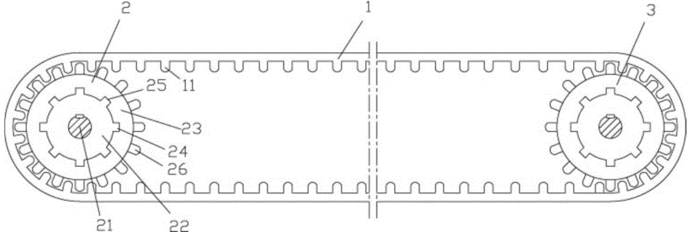
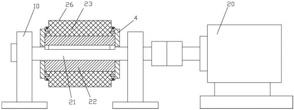
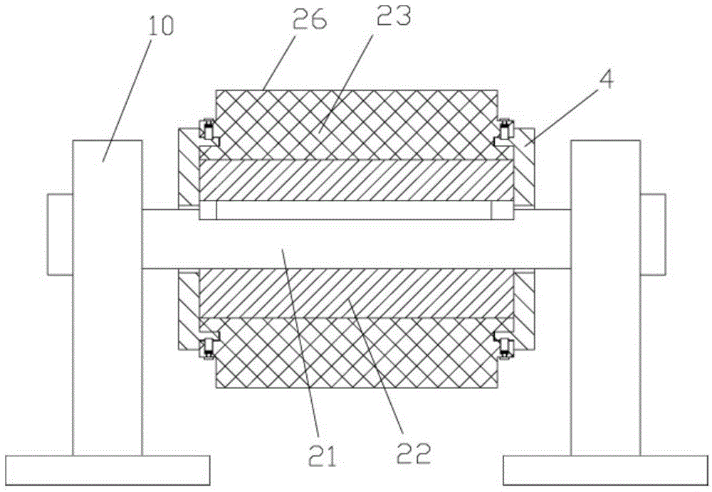
[0022] Examples, see e.g. Figures 1 to 5 As shown, a conveying device for rotating shaft processing includes a conveying belt 1, and the conveying belt 1 is tensioned on the main driving wheel 2 and the driven driving wheel 3. The main driving wheel 2 and the driven driving wheel 3 have the same structure, and they include a rotating shaft 21. The central wheel 22 and the outer rotating wheel 23, the rotating shaft 21 is fixed in the central through hole of the central wheel 22 through a key connection, the two ends of the rotating shaft 21 protrude from the central wheel 22, and the outer wall of the central wheel 22 has a plurality of protrusions 24 The inner side wall of the outer rotating wheel ...


PUM


Abstract

The invention discloses a shaft machining conveyer comprising a conveying belt. The conveying belt is tensioned on a main transmission wheel and an auxiliary transmission wheel. The main transmission wheel and the auxiliary transmission wheel are identical in structure. Each of the main transmission wheel and the auxiliary transmission wheel comprises a spindle, a central wheel and an outer rotating wheel; the spindle is fixed to a central through hole of the central wheel by key connecting and fixing; two ends of the spindle extend out of the central wheel; the outer wall of the central wheel is provided with a plurality of protrusions; the inner wall of the outer rotating wheel is provided with a plurality of grooves; the central wheel is nested in the outer rotating wheel; the protrusions are inserted into the grooves; the outer wall of the outer rotating wheel is provided with a plurality of elongated protrusions evenly distributed around the center axis of the outer rotating wheel; the inner wall of the conveying belt is provided with a plurality of rotating protrusions which fit the elongated protrusions; the conveying belt meshes with the outer wall of the outer rotating wheel. The shaft machining conveyer allows automatic conveying of shafts, the shafts never collide one another, the main transmission wheel and the auxiliary transmission wheel are simple in structure, and the outer rotating wheel is convenient to change.

Description

Technical field: [0001] The invention relates to the technical field of machining, and more specifically relates to a conveying device for machining a rotating shaft. Background technique: [0002] When the existing shaft workpieces are processed, the shafts are generally placed on the box, and the processed shaft workpieces are transported to the grinding machine by tools such as carts, and then manually loaded for processing, which is inefficient and the shafts The workpieces are generally placed in a box in a pile. During transportation, there will be bumps between two adjacent shaft workpieces, which will affect their quality. When the bumps are serious, they cannot be removed by grinding machines. It is scrapped, and the scrap rate increases. [0003] In order to solve this problem, the conveyor belt is currently used for transmission to reduce the occurrence of this problem. However, the conveyor belt is transmitted through two rotating wheels. The outer surface of th...

Claims


Application Information

Patent Timeline
Patent Type & Authority Applications(China)
IPC IPC(8): B65G23/06B65G15/42B24B41/00
CPCB65G15/42B65G23/06B24B41/00B65G2812/02148Y02P70/10
Inventor 杨建华
Owner DONGGUAN TIANHE ELECTROMECHANICAL DEV CO LTD
Learn More