Rapid-clamping rocking handle and lifting device with same

A lifting device and fast technology, applied in the field of lifting device and fast clamping crank handle, can solve problems such as personal injury, sudden drop of lifting items without consideration, crank handle falling off, etc., to achieve convenient use and avoid heavy objects Sudden drop, quick clamping effect

Active Publication Date: 2015-03-25
凯迈(洛阳)测控有限公司
View PDF8 Cites 1 Cited by
  • Summary
  • Abstract
  • Description
  • Claims
  • Application Information

AI Technical Summary

Problems solved by technology

[0003] However, the structure of the existing fast clamping handles is relatively simple, which can only realize the transmission of torque, and does not consider the sudden drop of the lifting object caused by the inversion of the handle during the lifting process, and lacks the design of the safety mechanism. During the lifting process of heavy objects, it is necessary to manually hold the operating handle all the time, or to set up a locking mechanism corresponding to the rotating shaft or the lifting input shaft of the lifting device, and rely on the locking mechanism to lock and position the rotating shaft after the crank stops.
However, additional locking mechanisms need to be operated separately after the weight is lifted into place, which is inconvenient to use and often requires at least two people to work together, wasting manpower
At the same time, the existing crank handle and the rotating shaft are generally detachably connected, and the crank handle may fall off during operation, which may easily cause personal injury and damage to items, and there are hidden dangers in operation

Method used


Image

  • Rapid-clamping rocking handle and lifting device with same
  • Rapid-clamping rocking handle and lifting device with same
  • Rapid-clamping rocking handle and lifting device with same

Examples


Embodiment Construction

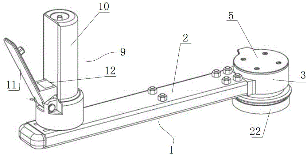
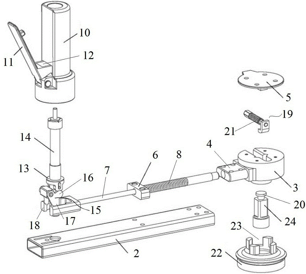
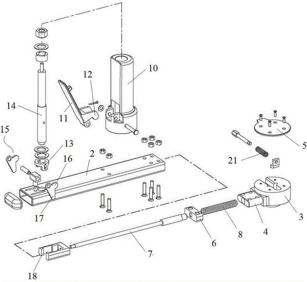
[0020] An embodiment of the fast clamping handle in the present invention is as Figure 1~Figure 3 As shown, it is a fast clamping handle used on a small lifting device. The lifting input shaft of the lifting device is fixedly connected with an input shaft 24 with a square shaft section. The fast clamping handle includes a sleeve for Set on the input shaft 24 and indirect transmission connection with the hoisting input shaft of the hoisting device to drive the power transmission handle 1 that the hoisting input shaft rotates, the anti-reverse end cover 22 for fixed connection with the main body of the hoisting device and the Operating handle 9 on the power transmission handle 1.

[0021] Four protrusions protrude from the end surface of the anti-reverse end cap 22 , and each protrusion is arranged at intervals along the circumferential direction to form stop grooves 23 uniformly distributed along the circumferential direction. The force transmission handle 1 includes a force ...


PUM


Abstract

The invention relates to a rapid-clamping rocking handle and a lifting device with the rapid-clamping rocking handle. The rapid-clamping rocking handle for lifting comprises a force transmission handle and an inverse-rotation-prevention end cover, wherein the force transmission handle is used for driving a lifting input shaft to rotate, and the inverse-rotation-prevention end cover is fixedly connected with a lifting device body. An inverse-rotation-prevention pin is arranged on the force transmission handle and moves in the direction perpendicular to the rotation axis of the force transmission handle in a guiding mode, a stopping groove is formed in the inverse-rotation-prevention end cover and used for inserting the inverse-rotation-prevention pin in the radial direction of the inverse-rotation-prevention end cover so that the stopping groove can be matched with the inverse-rotation-prevention pin in the circumferential direction in a stopping mode, and the inverse-rotation-prevention pin has a locking position and an unlocking position in the guiding moving travel of the inverse-rotation-prevention pin, wherein the locking position is inserted into the stopping groove, and the unlocking position withdraws from the stopping groove. The force transmission handle is provided with an elastic resetting mechanism used for exerting acting force on the inverse-rotation-prevention pin to move the inverse-rotation-prevention pin toward the unlocking position, and is further provided with an unlocking device connected with the inverse-rotation-prevention pin in a transmission mode. The unlocking device is provided with an operation position and a releasing position, wherein the operation position corresponds to the unlocking position of the inverse-rotation-prevention pin, and the releasing position corresponds to the locking position of the inverse-rotation-prevention pin. The rocking handle can conveniently achieve locking, and it is avoided that because the rocking handle inversely rotates, heavy objects suddenly fall off.

Description

technical field [0001] The invention relates to a fast locking crank handle and a lifting device using the rotating handle. Background technique [0002] In some occasions, it is often necessary to use a lifting device to manually lift heavy objects, especially a small lifting device. The power input end of this type of lifting device is generally equipped with a rotating shaft, and the rotating shaft passes through conventional structures such as square shaft structures, pin ferrule structures, and flange structures. The transmission structure is connected with a rocker. The rocker includes an operating handle whose rotation axis is parallel to the axis of the rotating shaft. When lifting heavy objects, hold the operating handle and turn the handle to drive the rotating shaft to lift the heavy object. [0003] However, the structure of the existing fast clamping handles is relatively simple, which can only realize the transmission of torque, and does not consider the sudden...

Claims


Application Information

Patent Timeline
Patent Type & Authority Applications(China)
IPC IPC(8): B66F13/00B66F3/00
CPCB66F13/00
Inventor 杜方张丹张家堂邹崇磊孙青锁李艳
Owner 凯迈(洛阳)测控有限公司
Why Eureka
Try Eureka