
Top air sealing device for optical fiber drawing
A furnace top gas and wire drawing technology, which is applied to glass fiber drawing devices, glass manufacturing equipment, manufacturing tools, etc., can solve the problems of increasing tower height and rod feeding stroke, poor consistency and stability, and inconvenient disassembly and assembly of furnaces, etc. problems, to achieve the effect of large diameter variation range, simple structure and low cost of use
- Summary
- Abstract
- Description
- Claims
- Application Information
AI Technical Summary
Problems solved by technology
Method used
Image

Examples
Embodiment Construction
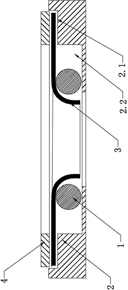
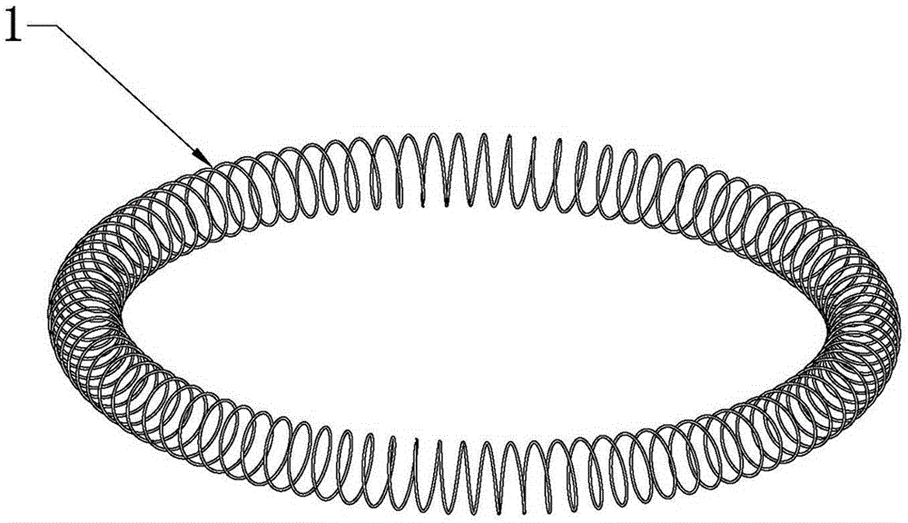
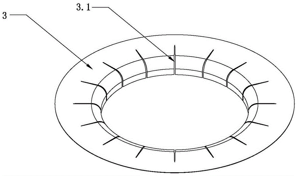
[0015] Such as figure 1 , figure 2 and image 3 As shown, a furnace top gas sealing device for optical fiber drawing is characterized in that it includes a self-tightening spring 1, an annular bottom plate 2, a graphite gas sealing ring 3 and an upper pressure ring 4; A high notch 2.1 and a low notch 2.2 are provided with several equally divided slits 3.1 along the circumferential direction at the inner ring mouth of the graphite gas seal ring 3; The outer side is arranged on the high notch 2.1 and pressed by the annular bottom plate 2, and the self-tightening spring 1 is arranged at the low notch 2.2 on the lower side of the inner ring mouth of the graphite air seal ring 3.
[0016] The working principle of the present invention is, as Figure 4 As shown, the present invention is installed at the entrance of the furnace roof of the optical fiber drawing furnace 5 through the annular bottom plate 2. During the process of sending the optical fiber preform rod 6 into...
PUM
 Abstract
Description
Claims
Application Information