Self-climbing wind power maintenance crane

A crane and self-climbing technology, applied in the field of self-climbing wind power maintenance cranes, can solve the problems of self-adaptive arm structure and complex movements, slow expansion and contraction speed of oil cylinders, and limited effective lifting weight, etc., so as to improve maintenance efficiency and equipment Small size, easy disassembly and transition effect

Pending Publication Date: 2020-04-10
上海锡华机械工程有限公司
View PDF1 Cites 1 Cited by
  • Summary
  • Abstract
  • Description
  • Claims
  • Application Information

AI Technical Summary

Problems solved by technology

[0006] The problem with this kind of self-climbing crane is that when climbing, the self-climbing device and the lifting device climb at the same time, resulting in excessive load on the self-climbing device and limited effective lifting capacity, and the oil cylinder telescopic and alternating step-by-step movement it adopts belongs to Intermittent movement, in order to reduce the impact of the start and stop of the oil cylinder when changing steps, the expansion and contraction speed of the oil cylinder is slow, and the climbing efficiency is low. If the hydraulic lock fails or the internal leakage of the hydraulic cylinder is too large, there is a risk of loosening the arm, and the climbing efficiency is low and the reliability is low

Method used


Image

  • Self-climbing wind power maintenance crane
  • Self-climbing wind power maintenance crane
  • Self-climbing wind power maintenance crane

Examples


no. 1 example

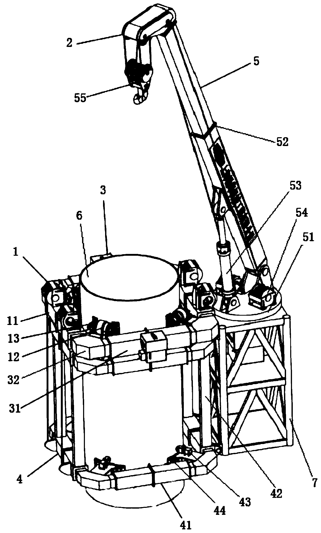
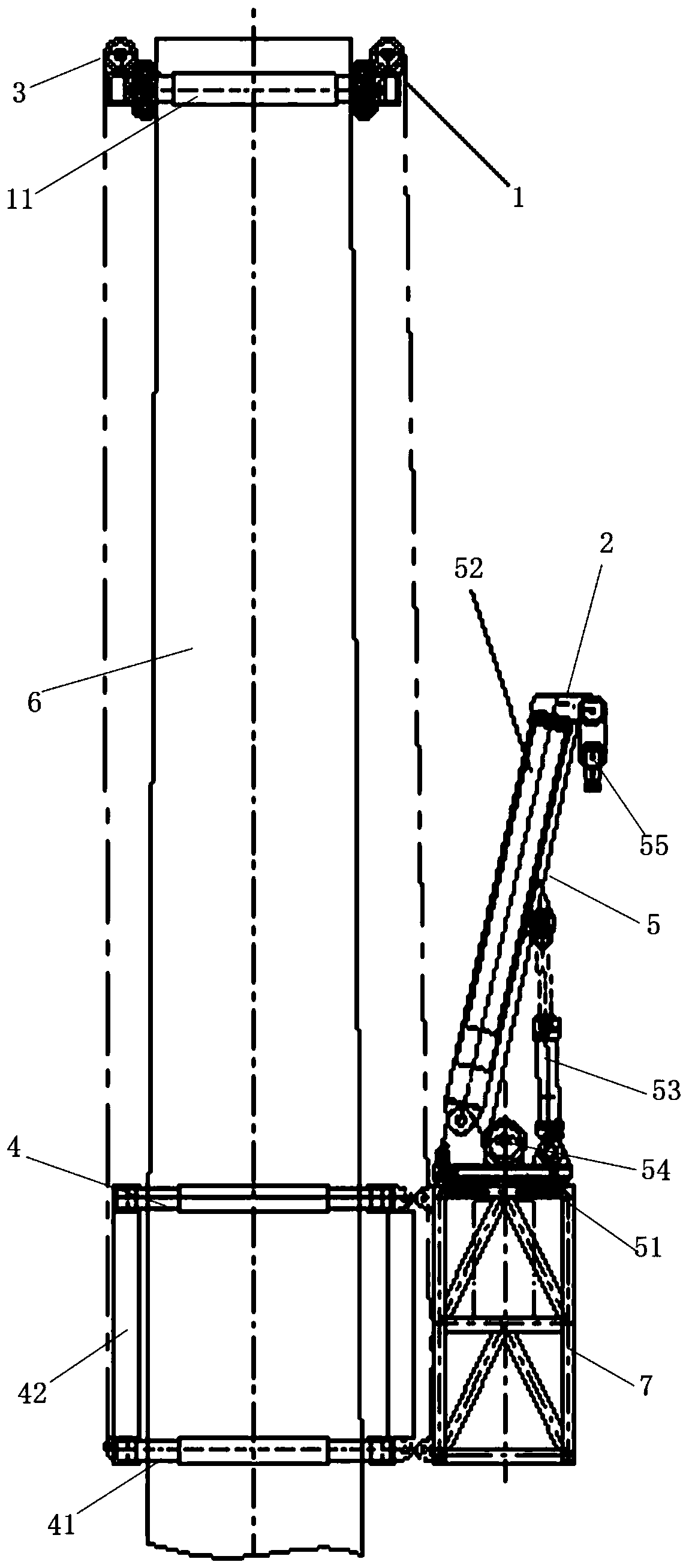
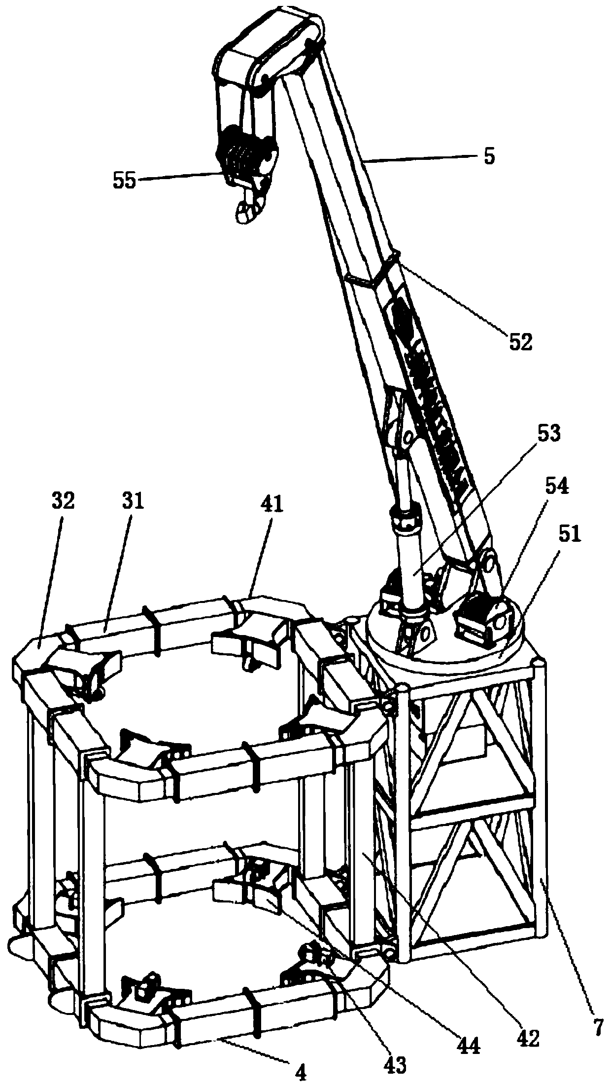
[0060] figure 1 It is a schematic diagram of the overall structure of a self-climbing wind power maintenance crane of the present invention, figure 2 It is a schematic diagram of the state of the self-climbing device traction lifting device in a self-climbing wind power maintenance crane of the present invention, and Fig. 3 is a structural schematic diagram of the lifting device in a self-climbing wind power maintenance crane of the present invention, Figure 4 It is a structural schematic diagram of the first embodiment of the first arm assembly and the second arm assembly in a self-climbing wind power maintenance crane of the present invention, Figure 5 It is a structural schematic diagram of the active wheel assembly in a self-climbing wind power maintenance crane of the present invention, Figure 6 It is a structural schematic diagram of a clamping assembly in a self-climbing wind power maintenance crane of the present invention, Figure 7 It is a structural schematic ...

Embodiment approach

[0070] In further embodiments of the present invention, please continue to refer to Figure 1 to Figure 7 As shown, the first arm assembly 11 and each second arm assembly 12 include: several telescopic arms 31 and several corner boxes 32, the several telescopic arms 31 and the several corner boxes 32 are arranged at intervals and connected in sequence to form a ring frame.

[0071] Preferably, the structures and principles of the first arm assembly 11 and the second arm assembly 41 are the same.

[0072] Preferably, the first arm assembly 11 and each second arm assembly 41 include: four telescopic arms 31 and a four-corner box 32, the four telescopic arms 31 and the four-corner boxes 32 are arranged at intervals and connected in sequence to form a square frame.

[0073] In a further embodiment of the present invention, each telescopic arm 31 includes: two first arms 311, two second arms 312 and two telescopic oil cylinders 313, and one end of the two first arms 311 is detachab...

no. 2 example

[0093] Figure 8 It is a structural schematic diagram of the second embodiment of the first arm assembly in a self-climbing wind power maintenance crane of the present invention, as shown in Figure 8 As shown, the main structure of the second embodiment is the same as that of the first embodiment, except that the first arm assembly 11 also includes: several guide rollers 17, two hydraulic reels 18 and at least two ropes 19, and several guide rollers 17 are all arranged on the outer wall of the first arm assembly 11, a number of guide rollers 17 are arranged at equal intervals along the outer circumference of the first arm assembly 11, two hydraulic rollers 18 are all arranged on the outer wall of the first arm assembly 11, two hydraulic Rollers 18 are all located between any two adjacent guide rollers 17, and each rope 19 is respectively connected with four guide rollers 17 and two hydraulic rollers 18 in transmission. Preferably, the hydraulic reel 18 is provided with a bra...


PUM


Abstract

The invention discloses a self-climbing type wind power maintenance crane, and belongs to the technical field of hoisting equipment. The self-climbing type wind power maintenance crane comprises a self-climbing device and a hoisting device. A hydraulic winch is arranged on the self-climbing device; the hoisting device comprises a climbing mechanism and a crane body, wherein the climbing mechanismis arranged under the self-climbing device, and the crane body is arranged on the side wall of the climbing mechanism; the self-climbing device is used for climbing to a preset working position alonga tower column, and is stably attached to the tower column; the hydraulic winch is used for pulling the climbing mechanism to ascend and descend along the tower column and driving the crane body to ascend and descend along the tower column at the same time; and the climbing mechanism is used for climbing along the tower column in the crane body pulling the climbing process and is stably attached to the tower column when the crane body reaches the operation position. The self-climbing type wind power maintenance crane is stable and efficient in climbing, good in reliability, small in equipmentsize, small in weather influence, convenient to assemble and disassemble and rapid in transition; the cost of wind power maintenance operation is effectively reduced; and the efficiency and income areimproved.

Description

technical field [0001] The invention relates to the technical field of lifting equipment, in particular to a self-climbing wind power maintenance crane. Background technique [0002] Currently in the period of rapid growth of the wind power industry, wind power equipment is constantly developing in the direction of high power and high towers. Wind farms are mostly located in high mountains, Gobi, wilderness, offshore, shallow seas and other areas with inconvenient transportation and harsh environments, resulting in the demand for wind turbines. The equipment requirements for installation and maintenance are getting higher and higher, the operation difficulty is getting more and more difficult, and the lifting cost has also risen sharply. [0003] The warranty period of wind turbines is generally 5 years. Almost all the fans installed during the explosive growth period have expired. The early design and manufacturing technology level is not high. After several years of operat...

Claims


Application Information

Patent Timeline
Patent Type & Authority Applications(China)
IPC IPC(8): B66C23/04B66C23/06B66C23/18B66C23/62
CPCB66C23/04B66C23/06B66C23/18B66C23/62B66C2700/03
Inventor 丁建国卢光辉王文彬马伟卜高峰陈玉超陈华兵
Owner 上海锡华机械工程有限公司
Why Eureka
Try Eureka