Quenching sensor with follow-up rotation for quenching continuous curved surface workpieces

A technology for quenching inductors and curved workpieces, applied in the direction of quenching devices, improvement of process efficiency, manufacturing tools, etc., can solve the problems of uneven quenching hardness, high cost, waste, etc., and achieve constant feed speed, convenient operation, and excellent structure simple effect

Inactive Publication Date: 2016-06-29
朝阳大隆机械制造有限公司
View PDF6 Cites 0 Cited by
  • Summary
  • Abstract
  • Description
  • Claims
  • Application Information

AI Technical Summary

Problems solved by technology

Relying on manual quenching by workers, the process is unstable during manual operation, resulting in uneven quenching hardness, uneven depth of hardened layer, and even microcracks on the surface of the quenched workpiece, which seriously affects the quenching effect and quality of the workpiece; relying on profiling quenching, is Manufacture an induction head that is similar in shape and structure to the surface of the workpiece to be quenched. Due to the variety of workpieces, the profiling induction head cannot meet the requirements of all specifications or shapes of workpieces.

Method used


Image

  • Quenching sensor with follow-up rotation for quenching continuous curved surface workpieces
  • Quenching sensor with follow-up rotation for quenching continuous curved surface workpieces
  • Quenching sensor with follow-up rotation for quenching continuous curved surface workpieces

Examples


Embodiment Construction

[0021] The present invention will be further described below in conjunction with the accompanying drawings and embodiments.

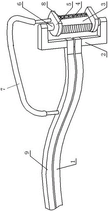
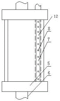
[0022] See attached Figure 1-4 The quenching inductor for continuous curved surfaces disclosed in the present invention includes an induction quenching head and a tension arm.

[0023] Tightening arm comprises tensioning arm upper arm 9 and tensioning arm lower arm 1, tensioning frame 2, rotary shaft 6. One end of the upper arm of the tension arm and the lower arm of the tension arm is connected with the frequency conversion pulse direct current power supply, and is fixed on the frame of the driving mechanism, and is driven by the driving mechanism to move. Their other ends are respectively vertically fixed with a frame body, and the two frame bodies form a tensioning frame 2 of a C-shaped structure, and the two free ends of the tensioning frame are welded and fixed to the rotary shaft respectively. The upper arm of the tensioning arm, the lower arm ...


PUM


Abstract

The invention relates to a follow-up rotary type quenching inductor for quenching a workpiece with a continuous curved surface. The follow-up rotary type quenching inductor comprises an induction quenching head and a tensioning arm, wherein one end of the upper arm of the tensioning arm and one end of the lower arm of the tensioning arm are connected with a DC frequency-conversion pulse power supply and are fixed on a driving mechanism rack, the other end of the upper arm of the tensioning arm and the other end of the lower arm of the tensioning arm are connected with a tensioning frame respectively, the tensioning frame is of a C-shaped structure, two free ends of the tensioning frame are connected with a rotating shaft respectively; the induction quenching head comprises metal sheets and blocking sheets, each metal sheet is of a D-shaped sheet structure, an axle hole and a water pipe through hole are formed in each metal sheet, a plurality of metal sheets are overlaid up and down to form an induction quenching head body, and the sections of all the metal sheets form an induction quenching head working surface; and the rotating shaft penetrates through the metal sheets and passes through the axle holes in the upper separation sheet and the lower separation sheet to be movably connected with the two ends of the tensioning frame. The induction quenching head has multiple functions, is adaptive to the quenching treatment of the continuous curved surfaces with various shapes and specifications, the quenching head can rotate and is normally perpendicular to the quenched curved surface, a motor is adjusted to achieve uniform feeding of the quenching head, and the constant feeding speed can be realized.

Description

technical field [0001] The invention relates to an induction hardening device, in particular to a rotatable inductor suitable for hardening the surface of a continuous curved workpiece. Background technique [0002] At present, the surface quenching of most continuous curved surface workpieces mostly depends on the manual quenching of operators or the production of profiling quenching induction heads. Relying on manual quenching by workers, the process is unstable during manual operation, resulting in uneven quenching hardness, uneven depth of hardened layer, and even microcracks on the surface of the quenched workpiece, which seriously affects the quenching effect and quality of the workpiece; relying on profiling quenching, is Manufacture an induction head that is similar in shape and structure to the surface of the workpiece to be quenched. Due to the variety of workpieces, the profiling induction head cannot meet the requirements of all specifications or shapes of workpi...

Claims


Application Information

Patent Timeline
Patent Type & Authority Patents(China)
IPC IPC(8): C21D9/00C21D1/62C21D1/10
CPCY02P10/25
Inventor 宫恩学
Owner 朝阳大隆机械制造有限公司
Why Eureka
Try Eureka