
Lock head and key

A lock and key technology, which is applied in the field of mechanical locks, can solve the problems of small number of keys, mutual opening, and poor practicability of the lock, so as to achieve a large amount of key codes on the lock, and it is not easy to open or crack each other Effect

Active Publication Date: 2015-03-25
四川王力安防产品有限公司
View PDF6 Cites 5 Cited by
  • Summary
  • Abstract
  • Description
  • Claims
  • Application Information

AI Technical Summary

Problems solved by technology

[0007] What the present invention aims to solve is the technical problem that the existing lock head is not very practical, the number of keys is small, and there are mutual openings, so as to provide a lock head and an adaptable lock head with strong practicability, a large increase in the number of keys and avoiding the phenomenon of mutual opening. key for the lock

Method used


Image

  • Lock head and key
  • Lock head and key
  • Lock head and key

Examples


Embodiment 1

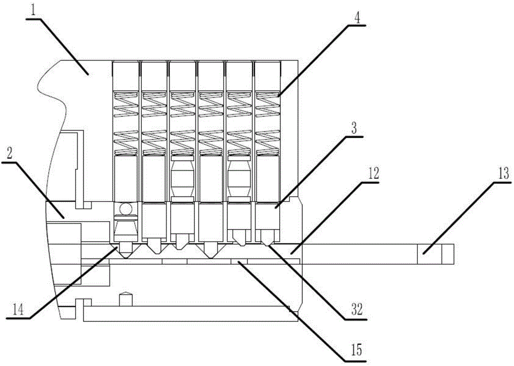
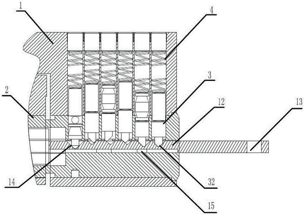
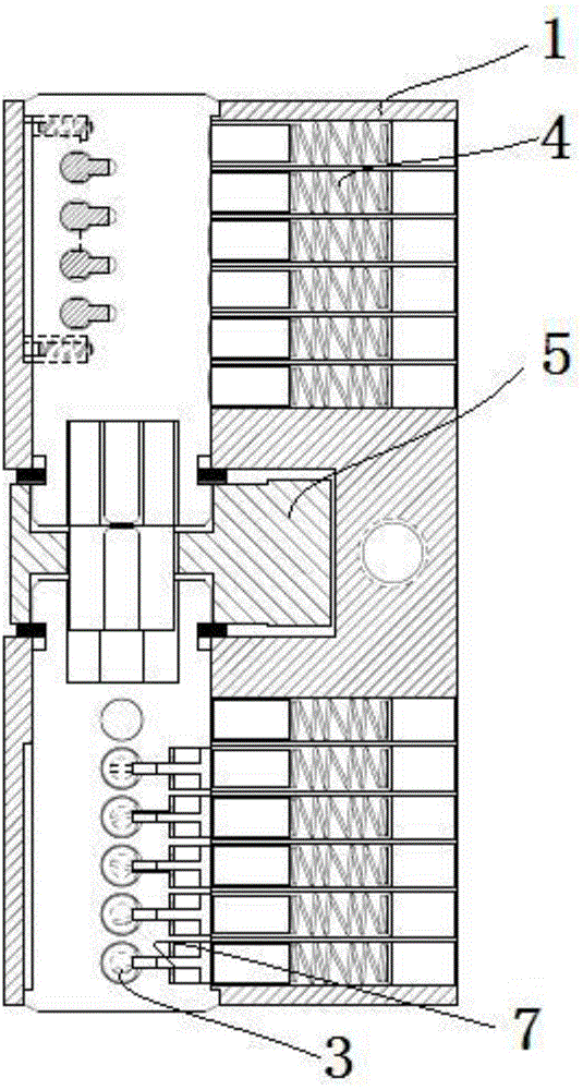
[0066] see Figure 1-17 , the present embodiment provides a lock head, including a housing 1 with an inner cavity, the inner cavity is preferably cylindrical in shape so as to facilitate the rotation of the core 2 in the inner cavity.

[0067] Such as figure 1 , figure 2 As shown, the core body 2 is rotatably arranged in the inner chamber of the housing 1, and the core body 2 is also provided with a key passage for the insertion of a key, so that when a matching key passes through the key passage, a keyway of the present invention is unlocked. When turning the lock, the key can drive the core 2 to rotate in the inner cavity.

[0068] Such as figure 1 , figure 2 As shown, the marbles include numbered marbles 3 arranged in the through holes of the core body, and flat-headed marbles arranged in the marble passages on the housing 1, wherein the marble passages should communicate with the core body. The holes are in the channel on the same axis in the locked state, or in the...

Embodiment 2

[0100] see Figure 18 , this embodiment provides a key for opening a lock head in Embodiment 1, including a key scale plate 12, a gripping portion 13 for holding the key scale plate 12 and a key set on the key scale plate 12. One side of the plate 12 is used to position the number pin 3 at the unlocking position of the tooth pattern groove 14, the position of the tooth pattern groove 14 should be set corresponding to the unlocking position of the number pin 3, and the tooth pattern groove The number of grooves 14 is at least not less than the number of the number pins 3, and the groove shape of the tooth flower groove 14 is set corresponding to the opposing end 32 of the number pins 3, so that the opposing end 32 is suitable for typing the number pins. Tooth flower groove 14 and can be positioned, Figure 18 As can be seen in the figure, the tooth pattern groove 14 is a wedge-shaped groove with different slotting directions, different groove shapes, and different length inter...


PUM


Abstract

The invention discloses a lock head. The lock head comprises a shell, a core, a number marble, a flat-end marble, a first eccentric compression piece and a dial wheel piece and further comprises a first positioning pin key, a first pin key groove formed in the inner wall of the shell, a second eccentric compression piece arranged between the first positioning pin key and the core, and a driving part arranged on the number marble, capable of being combined with the first positioning pin key when the number marble rotates along with the core and used for driving the first positioning pin key to be rotated out of the first pin key groove. The eccentric compression force of the second eccentric compression piece makes the first positioning pin key embedded and reset in the direction of the first pin key groove, the number marble can provide multiple secret key codes when axially rotating in the key insertion process and when the core axially moves in combination with the change of the length of the number marble, and therefore the extremely good technical opening preventing capacity is achieved.

Description

technical field [0001] The invention relates to a lock head and a key, belonging to the field of mechanical locks. Background technique [0002] People use locks to lock objects with accommodating spaces such as doors, safes or drawers to restrict others from entering or opening. Usually, common locks consist of a lock head and a lock that can be locked out and locked back through a series of transmission mechanisms. It is composed of a tongue. The general lock head is to unlock the core and the shell after the number pin is lifted by the key tooth, so that the core can rotate relative to the shell, and drive the cam linked with the core to toggle the unlock switch. It is called "pin lock". The existing "pin lock" makes the number pins into different heights to correspond to the key teeth of different heights. Only the change in the height direction makes the key quantity very limited. Different locks The phenomenon of using the same key to open each other happens from time...

Claims


Application Information

Patent Timeline
IPC IPC(8): E05B27/10E05B31/00E05B19/08E05B15/14
Inventor 彭建新吕策
Owner 四川王力安防产品有限公司
Learn More