A circulating water supply system

A technology for water supply systems and water inlets, which can be used in water conservancy projects, hydropower stations, mechanical equipment, etc., and can solve the problem of high cost of dams

Inactive Publication Date: 2017-01-04
刘光
View PDF5 Cites 0 Cited by
  • Summary
  • Abstract
  • Description
  • Claims
  • Application Information

AI Technical Summary

Problems solved by technology

[0004] In view of this, the first object of the present invention is to provide a circulating water supply system, the structural design of which can effectively solve the problem that the cost of building a dam is high

Method used


Image

  • A circulating water supply system
  • A circulating water supply system
  • A circulating water supply system

Examples


Embodiment Construction

[0042] The first object of the present invention is to provide a circulating water supply system whose structural design can effectively solve the problem of high cost of building a dam.

[0043] The following will clearly and completely describe the technical solutions in the embodiments of the present invention with reference to the accompanying drawings in the embodiments of the present invention. Obviously, the described embodiments are only some, not all, embodiments of the present invention. Based on the embodiments of the present invention, all other embodiments obtained by persons of ordinary skill in the art without making creative efforts belong to the protection scope of the present invention.

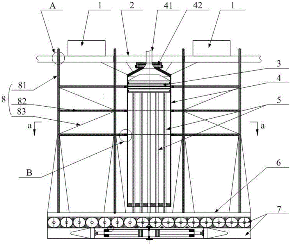
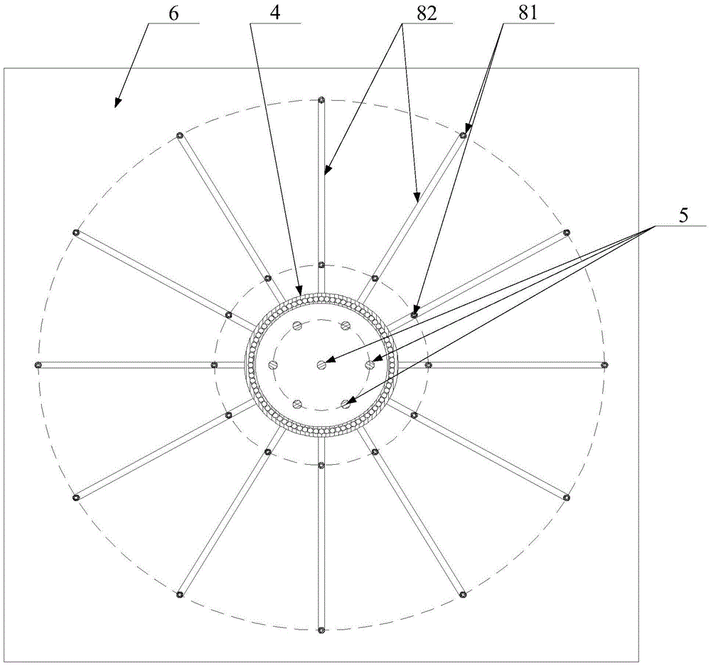
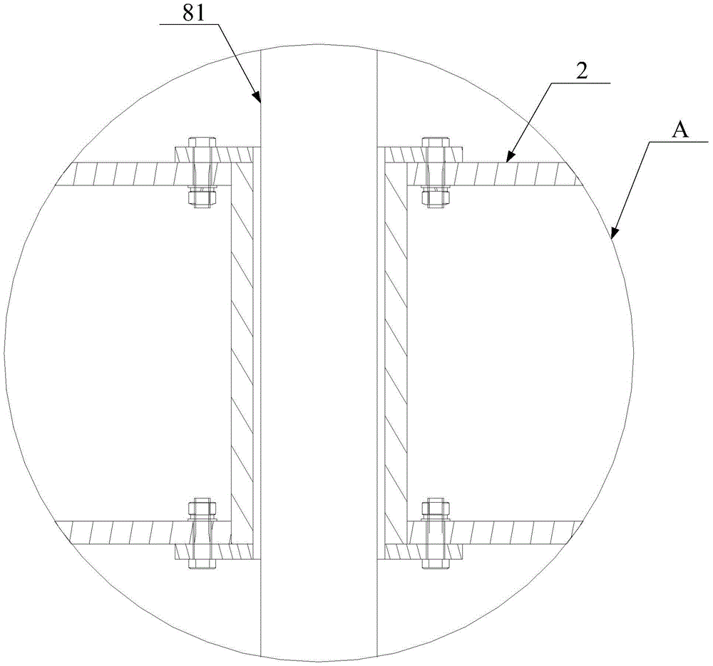
[0044] see Figure 1-Figure 8, The circulating water supply system provided by the present invention includes a stable platform 2 , a cylinder body 4 , a first piston 3 , a piston rod 5 , a buoyancy tube 7 and a driving device 9 . Wherein, the cylinder body 4 is located bel...


PUM


Abstract

The invention discloses a circulating water supply system comprising a stable platform, a cylinder body, a first piston, a piston rod, a buoyancy tube and a driving device. Wherein, the cylinder body is located below the stable platform, and the upper end of the cylinder body is fixedly connected with the stable platform. The upper end of the cylinder body is provided with a water inlet and a water outlet channel, and a water inlet valve is arranged at the water inlet. The first piston is in sealing contact with the inner wall of the cylinder, and the first piston can slide up and down along the inner wall of the cylinder, and the upper end of the piston rod is fixedly connected with the first piston. The buoyancy tube is relatively fixed to the lower end of the piston rod, and the buoyancy tube has a buoyancy chamber, the buoyancy chamber has a water outlet and a vent, and also includes a trachea communicated with the vent of the buoyancy chamber and the trachea is provided with a valve, and the driving device can turn the buoyancy chamber water in the drain. The structural design of the circulating water supply system can effectively solve the problem of high cost of building a dam.

Description

technical field [0001] The invention relates to the technical field of hydroelectric power generation, and more specifically, relates to a circulating water supply system. Background technique [0002] Hydroelectric power generation refers to the use of rivers, lakes, etc. to flow water with potential energy from high places to low places, convert the potential energy contained in it into kinetic energy of water turbines, and then drive generators to generate electricity through water turbines. Use hydraulic power to drive hydraulic machinery to rotate, convert water energy into mechanical energy, and then convert mechanical energy into electrical energy. The essence of hydroelectric power generation is the process of converting the potential energy of water into mechanical energy, and then converting the mechanical energy into electrical energy. The amount of hydroelectric power generation is closely related to water flow and water drop. If the water flow is large and the ...

Claims


Application Information

Patent Timeline
Patent Type & Authority Patents(China)
IPC IPC(8): F04B9/08F03B11/00E02B9/00
Inventor 刘光
Owner 刘光
Why Eureka
Try Eureka