Optical waveguide device
a technology of optical waveguide and optical waveguide device, which is applied in the field of optical modulation module, can solve the problems of difficult disassembly of optical waveguide device and exchange of optical waveguide with new optical waveguide, and inability to obtain long-term stable operation, etc., and achieve the effect of reducing or eliminating the photorefractive
- Summary
- Abstract
- Description
- Claims
- Application Information
AI Technical Summary
Benefits of technology
Problems solved by technology
Method used
Image
Examples
first embodiment
[0054]First, a first embodiment of the present invention will be described.
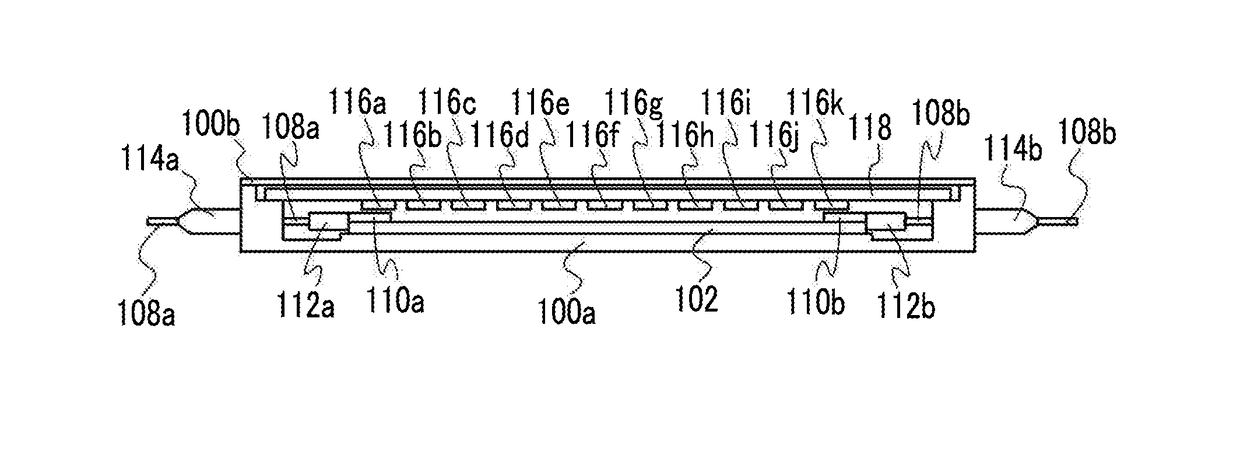
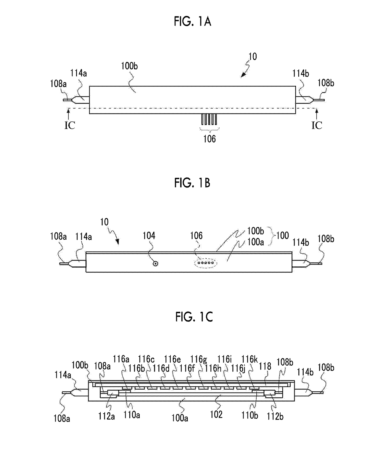
[0055]FIG. 1A is a top view illustrating the constitution of an optical waveguide device according to the first embodiment of the present invention, FIG. 1B is a front view illustrating the constitution of an optical waveguide device according to the first embodiment of the present invention, and FIG. 1C is a sectional view in a direction of an arrow IC illustrating the constitution of an optical waveguide device according to the first embodiment of the present invention.
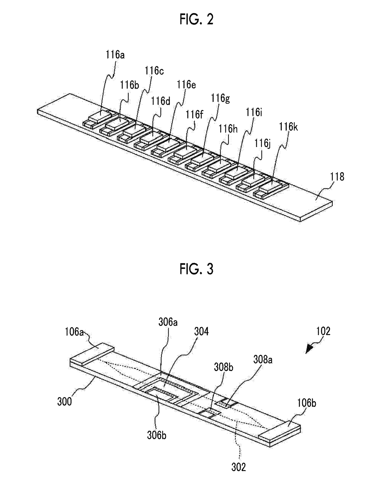
[0056]An optical waveguide device 10 has a housing package 100 made up of a case 100a and a cover 100b and an optical functional element 102 accommodated in the housing package 100. The optical functional element 102 is an optical modulation element constituted of an LN substrate, a Mach-Zehnder-type optical waveguide formed on the surface (the upper side surface of the optical functional element 102 in the drawing) of the LN substrate, and e...
second embodiment
[0073]Next, a second embodiment of the present invention will be described. In an optical waveguide device of the present embodiment, instead of disposing a plurality of light sources such as LEDs or the like in parallel as the light sources that emit ultraviolet light or violet light, light from a single light source of ultraviolet light or violet light is irradiated on almost all or part of the region of the LN substrate of the optical functional element through a light-guiding plate.
[0074]FIG. 4A is a top view illustrating the constitution of the optical waveguide device according to the second embodiment of the present invention, FIG. 4B is a front view illustrating the constitution of the optical waveguide device according to the second embodiment of the present invention, and FIG. 4C is a sectional view in a direction of an arrow IVC illustrating the constitution of the optical waveguide device according to the second embodiment of the present invention. Meanwhile, in FIG. 4A,...
third embodiment
[0079]Next, a third embodiment of the present invention will be described. An optical waveguide device of the present embodiment is constituted of an optical functional unit having an optical functional element accommodated in a housing package and a light source unit having a light source for irradiating ultraviolet light or violet light on an LN substrate of the optical functional element in the optical functional unit. In addition, ultraviolet light or violet light emitted from the light source unit is irradiated on the LN substrate of the optical functional element accommodated in the optical functional unit through a window provided in the housing package of the optical functional unit.
[0080]FIG. 5A is a top view illustrating the constitution of the optical waveguide device according to the first embodiment of the present invention, FIG. 5B is a front view illustrating the constitution of the optical waveguide device according to the first embodiment of the present invention, a...
PUM
| Property | Measurement | Unit |
|---|---|---|
| wavelengths | aaaaa | aaaaa |
| wavelength | aaaaa | aaaaa |
| communication wavelength band | aaaaa | aaaaa |
Abstract
Description
Claims
Application Information
 - R&D
- Intellectual Property
- Life Sciences
- Materials
- Tech Scout
- Unparalleled Data Quality
- Higher Quality Content
- 60% Fewer Hallucinations
Browse by: Latest US Patents, China's latest patents, Technical Efficacy Thesaurus, Application Domain, Technology Topic, Popular Technical Reports.
© 2025 PatSnap. All rights reserved.Legal|Privacy policy|Modern Slavery Act Transparency Statement|Sitemap|About US| Contact US: help@patsnap.com


