Experimental device for simulating operation of medium in cryogenic pump

An experimental device and cryogenic pump technology, applied in pump control, non-variable pumps, machines/engines, etc., can solve problems such as the inability to directly observe the operation process of the medium

Pending Publication Date: 2022-02-15
CNOOC GAS & POWER GRP +1
View PDF0 Cites 0 Cited by
  • Summary
  • Abstract
  • Description
  • Claims
  • Application Information

AI Technical Summary

Problems solved by technology

[0004] The purpose of the present invention is to provide an experimental device for simulating the operation of the medium in the

Method used


Image

  • Experimental device for simulating operation of medium in cryogenic pump
  • Experimental device for simulating operation of medium in cryogenic pump
  • Experimental device for simulating operation of medium in cryogenic pump

Examples


Embodiment 1

[0035] Example 1: An experimental device for simulating the operation of a medium in a cryopump

[0036] Embodiment 1 provides an experimental device for simulating the operation of a medium in a cryopump, and its structure will be described in detail below.

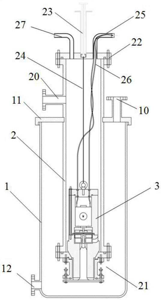
[0037] refer to figure 1 with Figure 4 , the experimental device for simulating the operation of the medium in the cryopump includes a storage tank 1, a pump well pipe 2 and a pump body 3,

[0038] The storage tank 1 is equipped with a cover plate 11, the pump well pipe 2 extends into the storage tank 1 through the cover plate 11, and the pump well pipe 2 is sealed and fixedly connected with the cover plate 11;

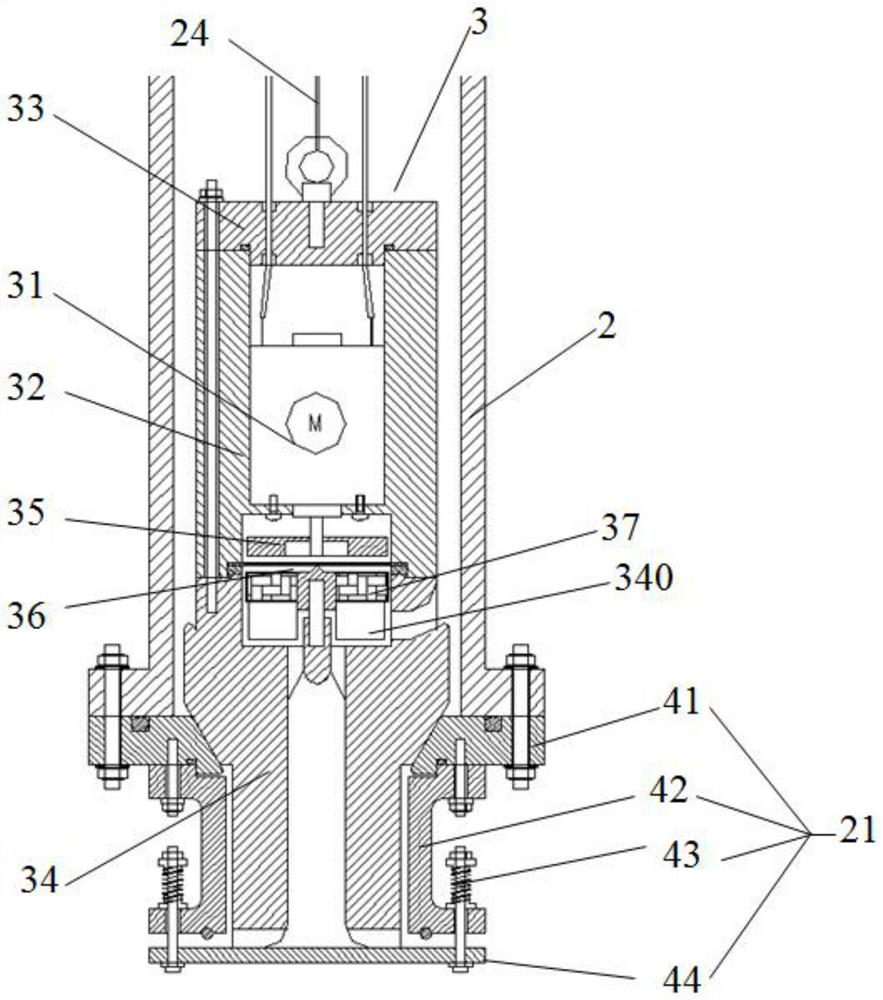
[0039] The bottom end and the top end of the pump well pipe 2 are respectively equipped with a bottom valve 21 and a top plate 22, and the pump body 3 can be suspended in the pump well pipe 2;

[0040] The cover plate 11 is provided with a liquid inlet 10, and the pump well pipe 2 above the cover plate 11 is...

Embodiment 2

[0063] Example 2: An experimental method for observing the operating state of different flow rates of liquid media flowing through the pump body

[0064] Embodiment 2 provides an experimental method for observing the operating state of liquid media with different flow rates flowing through the pump body. The experimental device provided in Embodiment 1 for simulating the operation of a medium in a cryopump is used. The experimental method includes the following steps:

[0065] Close the liquid discharge port 12, inject liquid medium into the liquid inlet 10, the liquid medium gathers at the bottom of the storage tank 1, overflows the bottom valve 21, until the liquid medium flows into the pump body 3 through the bottom valve 21;

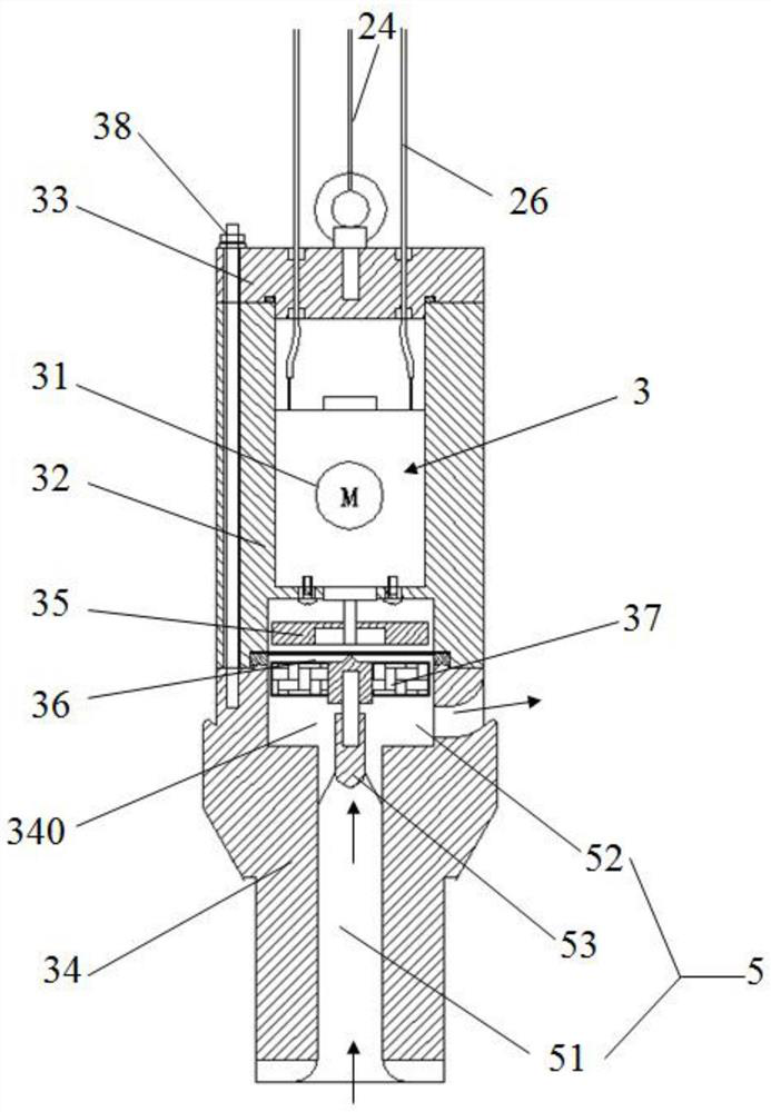
[0066] Start the pump body 3, the wire 26 introduces the current into the DC motor 31, and the rotation of the DC motor 31 drives the rotation of the permanent magnet 35;

[0067] The permanent magnet 35 interacts with the heteropolar permanent magne...

Embodiment 3

[0072] Example 3: An experimental method for simulating pump body disassembly and medium replacement

[0073] Embodiment 3 provides an experimental method for simulating pump disassembly and medium replacement. The experimental device for simulating the operation of a medium in a cryopump provided in Embodiment 1 is used. The experimental method includes the following steps:

[0074] Turn off the power supply, and the pump body 3 stops running;

[0075] Pull the needle piston 23 upwards, connect the sling 24 to lift the pump body 3, the spring assembly 43 pulls the valve plate 44 upwards, the valve plate 44 contacts the seal on the lower valve body 20, and the bottom valve 21 realizes sealing;

[0076] Lock the position of the needle piston 23, suspend the pump body 3 in the pump well pipe 2, and close the valve on the liquid outlet 20;

[0077] Use an air compressor to inject air into the gas injection port 27, the air is injected into the pump well pipe 2, and the air press...


PUM


Abstract

The invention discloses an experimental device for simulating operation of a medium in a cryogenic pump. The experimental device comprises a storage tank, a pump well pipe and a pump body, wherein the pump well pipe extends into the storage tank, and the pump body can be suspended in the pump well pipe; and the tank body of the storage tank and the pipe body of the pump well pipe are transparent. According to the experimental device for simulating operation of the medium in the cryogenic pump, the operation state of the pump and the sealing condition of a bottom valve can be observed from the outside of a container, and the movement condition of the medium in the pump well pipe can be observed; and through long-term operation of the liquid medium, long-term observation can be carried out. The experimental device can be popularized and applied to process simulation observation in the field of immersed pumps in low-temperature tanks.

Description

technical field [0001] The invention relates to the technical field of cryopumps, in particular to an experimental device for simulating the operation of a medium in a cryopump. Background technique [0002] The lowest temperature of the submersible pump in the low-temperature tank operates at -196°C, and it can transport LNG, LPG, LN2, etc., all of which belong to the low-temperature environment and contain certain dangerous media inside. [0003] Different from the standard pump, the submersible pump in the cryogenic tank is immersed in the medium, and can only be tested with the medium, and the test process cannot be observed. In actual use, the submersible pump in the cryogenic tank is installed in the cryogenic storage tank, and the operating status of the pump cannot be directly observed. Contents of the invention [0004] The object of the present invention is to provide an experimental device for simulating the operation of a medium in a cryopump, so as to solve t...

Claims


Application Information

Patent Timeline
IPC IPC(8): F04D27/00
CPCF04D27/001
Inventor 明红芳张超陈海平肖立黄宇许佳伟隋成君倪乃坤张娜冷志强
Owner CNOOC GAS & POWER GRP
Why Eureka
Try Eureka