
Aqueous carbon nanotube applicator liquids and methods for producing applicator liquids thereof

a carbon nanotube and applicator liquid technology, applied in the field of application liquids, can solve the problems of difficult derivatizing agent removal, difficult to remove derivatizing agent, and difficult to include or incorporate swnt as part of standard microelectronic fabrication process

Active Publication Date: 2006-09-14
ZEON CORP
View PDF47 Cites 126 Cited by
  • Summary
  • Abstract
  • Description
  • Claims
  • Application Information

AI Technical Summary

Benefits of technology

[0017] There remains a further need for methods that meet the criteria outlined above for low toxicity, purity, cleanliness, ease of handling and scalability.

Problems solved by technology

However, the inclusion or incorporation of the SWNT as part of standard microelectronic fabrication process has faced challenges due to a lack of a readily available application method compatible with existing semiconductor equipment and tools and meeting the stringent materials standards required in the electronic fabrication process.
Individual nanotubes may be used as conducting elements, e.g. as a channel in a transistor, however the placement of millions of catalyst particles and the growth of millions of properly aligned nanotubes of specific length presents serious challenges.
Nanotubes may be derivatized in order to facilitate bringing the tubes into solution, however in uses where pristine nanotubes are necessary, it is often difficult to remove the derivatizing agent.
Even when removal of the derivatizing agent is not difficult, such removal is an added, time-consuming step.
The solutions are stable but the solvents have the disadvantage of not solubilizing clean carbon nanotubes which are free of amorphous carbon.
Polymer wrapping usually affects sheet resistance of the SWNT network and may not be appropriate for electronic applications where low sheet resistance is desired.
While these approaches were successful in solubilizing the SWNTs in a variety of organic solvents to practically relevant levels, all such attempts resulted in the depletion of the π electrons that are essential to retain interesting electrical and optical properties of nanotubes.
While this type of approach has helped to retain the electrical conductivity and optical properties of the SWNTs, most such methods leave halogens or alkali metals or polymeric residues, which tend to severely hamper any meaningful use in microelectronic fabrication facilities.

Method used


Image

  • Aqueous carbon nanotube applicator liquids and methods for producing applicator liquids thereof
  • Aqueous carbon nanotube applicator liquids and methods for producing applicator liquids thereof
  • Aqueous carbon nanotube applicator liquids and methods for producing applicator liquids thereof

Examples


example 1

[0068] This example describes the purification of nanotubes.

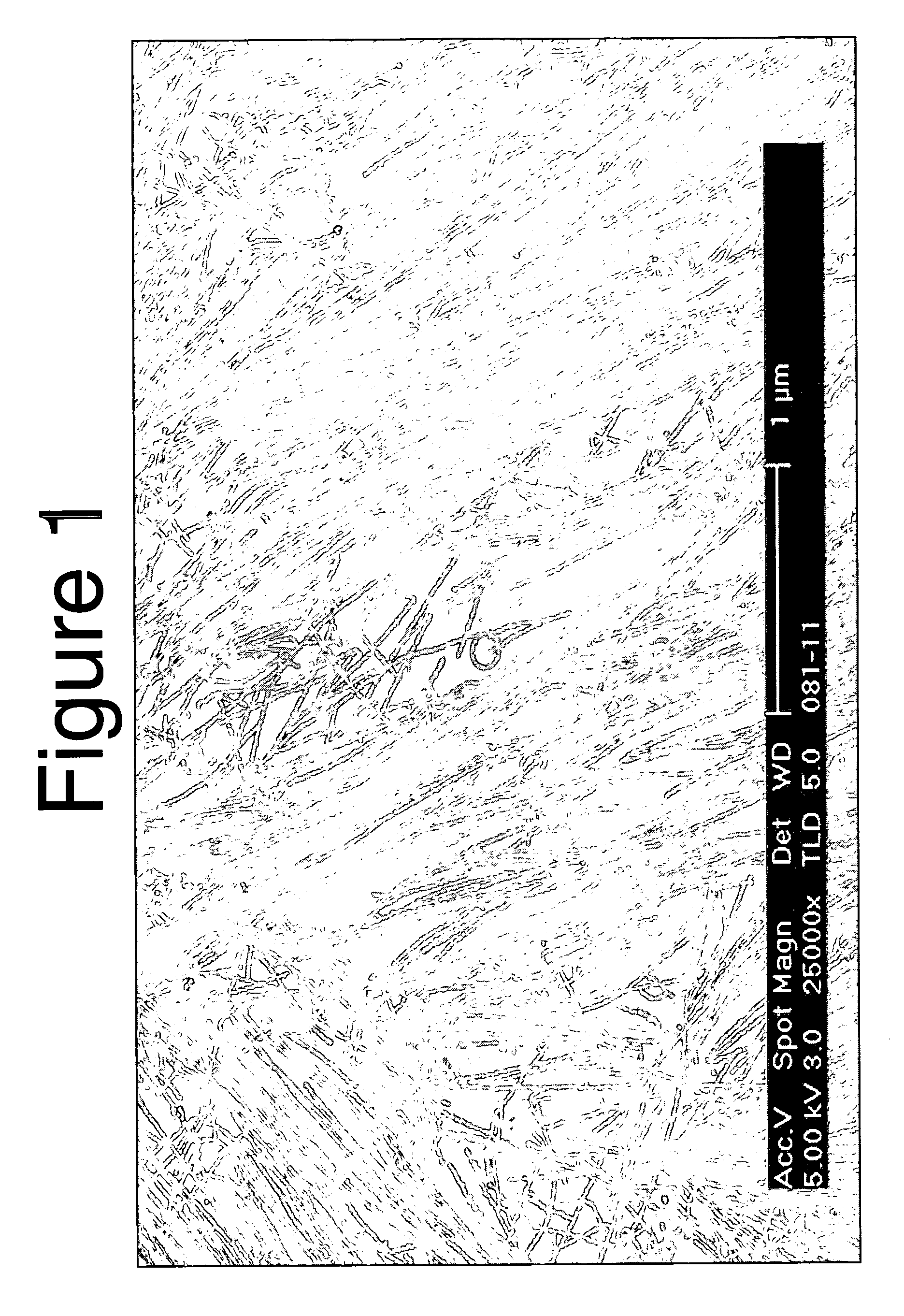
[0069] Single-walled carbon nanotubes (SWNTs) were purified by mixing 1 g of carbon nanotubes with a 125 mL:125 mL mixture of 15 M nitric acid (HNO3):DI water. The nanotube:nitric acid:DI mixture was stirred for 8 hours and refluxed for 12 hours at 125° C. After purification, the 250 mL nanotube:nitric acid solution was diluted with 7 parts DI water (˜1.8 L). The pH of the solution was adjusted to 1.5±0.1 by dropwise addition of concentrated NH4OH ([c]˜35%). The solution was then sonicated for 60 minutes in a chilled sonication bath at 4-5° C. Once sonication was completed, cross-flow filtration was then performed with a dedicated 0.5 micron ceramic membrane. The filtration was performed until the liquid that passes through the pores of the filter membrane obtained a pH of 4.0. This liquid is called a permeate and was rejected. The liquid that does not pass through the pores of the filter membrane is called a retentate and...

example 2

[0073] In addition to the examples given above, various pre-oxidation schemes were also used to purify the carbon nanotubes. Without being bound to theory, pre-oxidation process may remove amorphous carbon impurities and also may crack open the graphitic shells that cover the metal catalysts, thereby rendering them accessible to subsequent acid treatment.

[0074] In one example, carbon nanotubes were purified by mixing 1 g of carbon nanotubes with 100 mL of 30% H2O2. The nanotube:hydrogen peroxide was refluxed for 3 h at 110° C. After the pre-oxidation step, the 100 mL nanotube:peroxide solution was diluted with 10 parts DI water (˜1L). The nanotube:peroxide:DI water slurry was sonicated for 60 minutes in a chilled sonication bath at 4-5° C. The slurry was then vacuum filtered over 5 micron Teflon filter membrane. The solid was collected from the top of the filter membrane and taken through the next processing steps, as described below.

[0075] After the pre-oxidation step described a...

example 3

[0078] This example describes a gas phase pre-oxidation of carbon nanotubes. For example, 1 g of carbon nanotubes were heated in a flow of nitrogen-oxygen mixture (2:1 ratio) at 350° C. for 12 h. The gas-phase pre-oxidized carbon nanotube material was taken through the nitric acid treatment, cross flow filtration and centrifugation steps as described in Example 2 to produce an applicator liquid.

[0079] The applicator liquid produced herein can also be used to form a component of NRAM memories, such as described in U.S. Pat. No. 6,919,592, entitled “Electromechanical Memory Array Using Nanotube Ribbons and Method for Making Same,” filed Jul. 25, 2001; U.S. Pat. No. 6,643,165, entitled “Electromechanical Memory Having Cell Selection Circuitry Constructed with Nanotube Technology,” filed Jul. 25, 2001; U.S. patent application Ser. No. 10 / 810,962, entitled “NRAM Bit Selectable Two-Drive Nanotube Array,” filed Mar. 26, 2004; and U.S. patent application Ser. No. 10 / 810,963, entitled “NRAM...


PUM


Abstract

Certain applicator liquids and method of making the applicator liquids are described. The applicator liquids can be used to form nanotube films or fabrics of controlled properties. An applicator liquid for preparation of a nanotube film or fabric includes a controlled concentration of nanotubes dispersed in a liquid medium containing water. The controlled concentration is sufficient to form a nanotube fabric or film of preselected density and uniformity.

Description

CROSS-REFERENCE TO RELATED APPLICATIONS [0001] This application claims the benefit under 35 U.S.C. §119(e) of U.S. Provisional Patent Application Nos. 60 / 636,673, filed Dec. 16, 2004, and 60 / 704,858, filed Aug. 2, 2005, both of which are assigned to the assignee of this application, and both of which are incorporated herein by reference in their entirety. [0002] This application is related to the following applications, all of which are assigned to the assignee of this application, and all of which are incorporated by reference in their entirety: [0003] Nanotube Films and Articles (U.S. Pat. No. 6,706,402) filed Apr. 23, 2002; [0004] Methods of Nanotube Films and Articles (U.S. Pat. No. 6,835,591) filed Apr. 23, 2002; and [0005] Patterning of Nanoscopic Articles (U.S. patent application Ser. No. 10 / 936,119) filed on Sep. 8, 2004.BACKGROUND [0006] 1. Technical Field [0007] This invention describes applicator liquids for use in the preparation of nanotube films. Such applicator liquid...

Claims


Application Information

Patent Timeline
IPC IPC(8): C01B31/02D01F9/127
CPCB82Y10/00B82Y30/00B82Y40/00C01B31/0253C01B31/026C01B2202/02C01B2202/28D06M10/02D06M11/50D06M11/55D06M11/64D06M2101/40H01L51/0003H01L51/0048Y10S977/845Y10S977/746C01B32/168C01B32/17H10K71/12H10K85/221
Inventor GHENCIU, ELIODOR G.HAN, TZONG-RU T.SIVARAJAN, RAMESHRUECKES, THOMASSEN, RAHULSEGAL, BRENT M.WARD, JONATHAN W.
Owner ZEON CORP
Learn More