Liquid immersion type exposure apparatus

a technology of exposure apparatus and liquid immersion, which is applied in the direction of photomechanical apparatus, instruments, printing, etc., can solve the problems of reducing the yield of semiconductor devices, and difficult to adjust the air curtain provided by compressed air, etc., and achieves the effect of high resolution

Inactive Publication Date: 2006-05-30
CANON KK
View PDF5 Cites 132 Cited by
  • Summary
  • Abstract
  • Description
  • Claims
  • Application Information

AI Technical Summary

Benefits of technology

[0013]It is another object of the present invention to provide an exposure apparatus by which mixture of bubbles into a liquid medium maintained between a substrate to be exposed and an optical element of a projection optical system, nearest to the substrate, is prevented effectively and by which pressure variation of the liquid medium is held low, that is, variation of refractive index of the liquid medium is held low, such that a high resolution is assured.

Problems solved by technology

In the structure shown in FIG. 7, adjustment of the air curtain provided by compressed airs is difficult to achieve, and there is a possibility that airs are mixed into the liquid medium.
Once bubbles are mixed into the liquid medium, it disturbs the exposure and thus the exposure transfer precision is degraded thereby.
This leads to a decrease of yield of semiconductor device production.
There is an additional problem that, since it is difficult to hold a constant pressure applied to the liquid by the air curtain, a change in the pressure inside the liquid medium causes a change of liquid density.
This results in degradation of the exposure transfer precision and, thus, a decrease of yield in the semiconductor device manufacture.
Additionally, there is a possibility that the liquid is scattered outwardly when mixed in the air flow of the air curtain.
Such liquid may cause damage of structural components of the exposure apparatus.
If it occurs actually, the operation of the exposure apparatus has to be stopped for repair or adjustment, and it results in a large decrease of productivity in the semiconductor device manufacture.
However, since the motion of the substrate includes acceleration and deceleration, it is difficult to adjust the liquid supplying rate and liquid collecting rate exactly at high precision in accordance with the moving speed.
If the liquid supplying rate and liquid collecting rate can not be adjusted at high precision, then it is difficult to maintain the pressure inside the liquid constant.
This results in degradation of the exposure transfer precision and, thus, a decrease of yield in the semiconductor device manufacture.
Furthermore, in the structure shown in FIG. 7 and in the structure disclosed in PCT International Publication WO99 / 49504, there is a common problem that, since the position for liquid supply and collection is restricted, the degree of freedom of the movement direction for the stepwise motion and scan motion is lowered.
If the degree of freedom of the driving direction of the stepwise motion or scan motion is low, it leads to a decrease of the throughput and thus a decrease of the productivity in the semiconductor device manufacture.

Method used


Image

  • Liquid immersion type exposure apparatus
  • Liquid immersion type exposure apparatus
  • Liquid immersion type exposure apparatus

Examples


embodiment 1

[Embodiment 1]

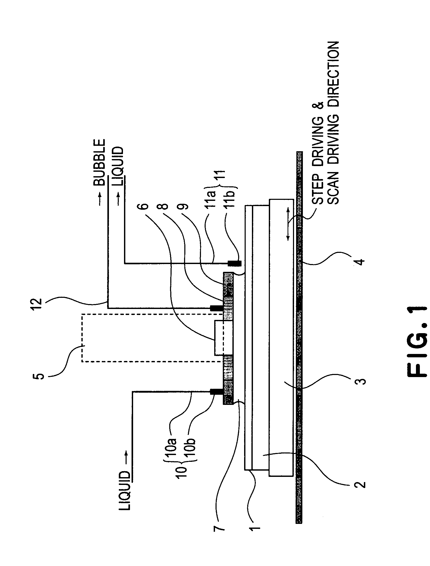
[0029]FIG. 1 is a schematic view showing a liquid immersion type exposure apparatus according to an embodiment of the present invention.

[0030]A substrate 1 that is an object onto which a circuit pattern or the like is to be transferred, is held by a substrate holder 2 in accordance with a vacuum holding method or an electrostatic holding method. The substrate holder 2 is mounted on a substrate stage 3 which is arranged to perform stepwise motion or scan motion to follow a stage base table 4. In the stepwise motion or scan motion, the substrate stage 3 is controlled on the basis of the result of measurement made through an autofocus (AF) sensor, not shown, so that the substrate 1 is held at a predetermined level (height).

[0031]On the other hand, the optical system includes a light source (not shown), an illumination system for illuminating a reticle having a transfer pattern with light from the light source, and a projection optical system mounted inside a barrel 5. The...

embodiment 2

[Embodiment 2]

[0041]FIG. 4 illustrates the structure around first to third porous materials in a liquid immersion type exposure apparatus according to another embodiment of the present invention.

[0042]In the first embodiment, a residual liquid medium 7 left on the substrate 1 is directly collected by the liquid collecting system 11. In this embodiment, on the other hand, a third porous material (liquid collecting material) 14 is provided additionally, so that a liquid 17 is collected through the third porous material 14. Description of similar structure and function of this embodiment, like those of the first embodiment, will be omitted to avoid duplication.

[0043]The third porous material 14 may have such property that it holds a liquid medium 7 on the basis of capillary phenomenon inside the porosity, like a sponge, and a similar porosity material as of the second porous member may be used. The liquid collecting system 11 is connected or approximately connected to the third porous ...

embodiment 3

[Embodiment 3]

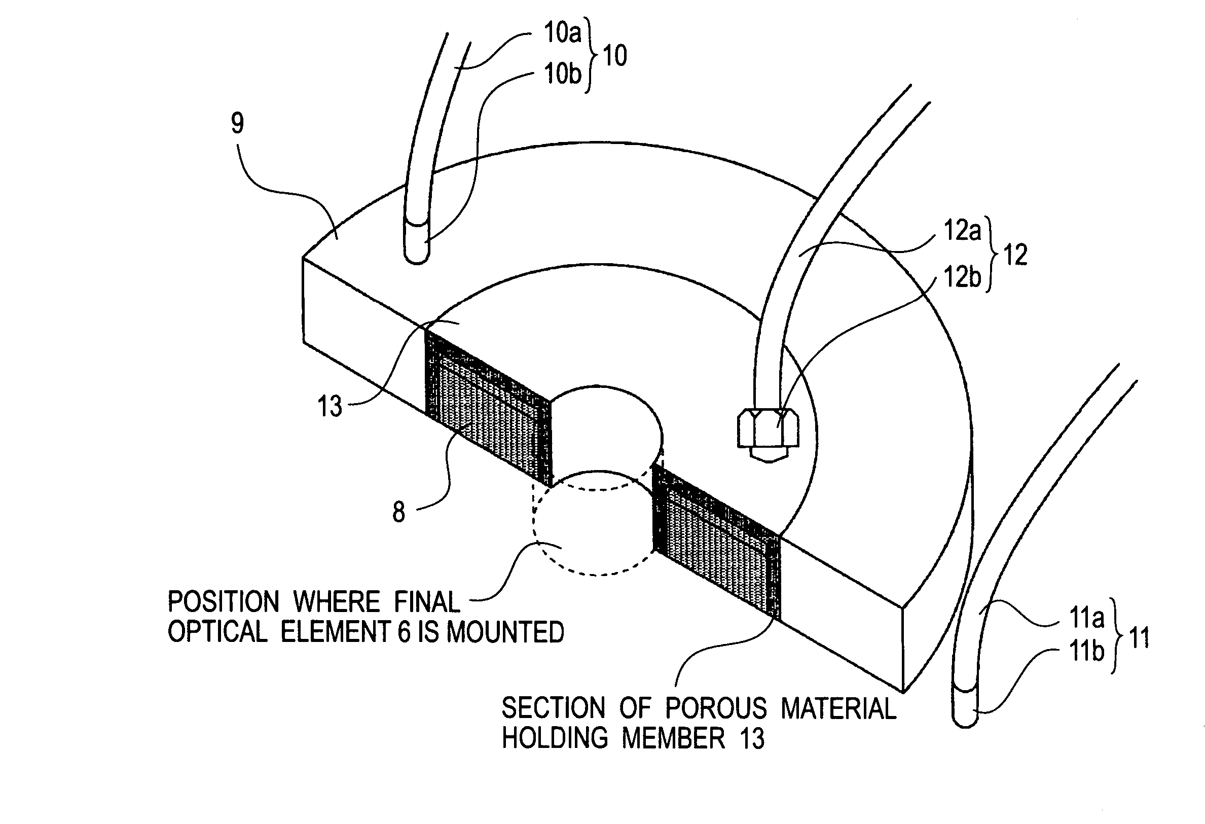
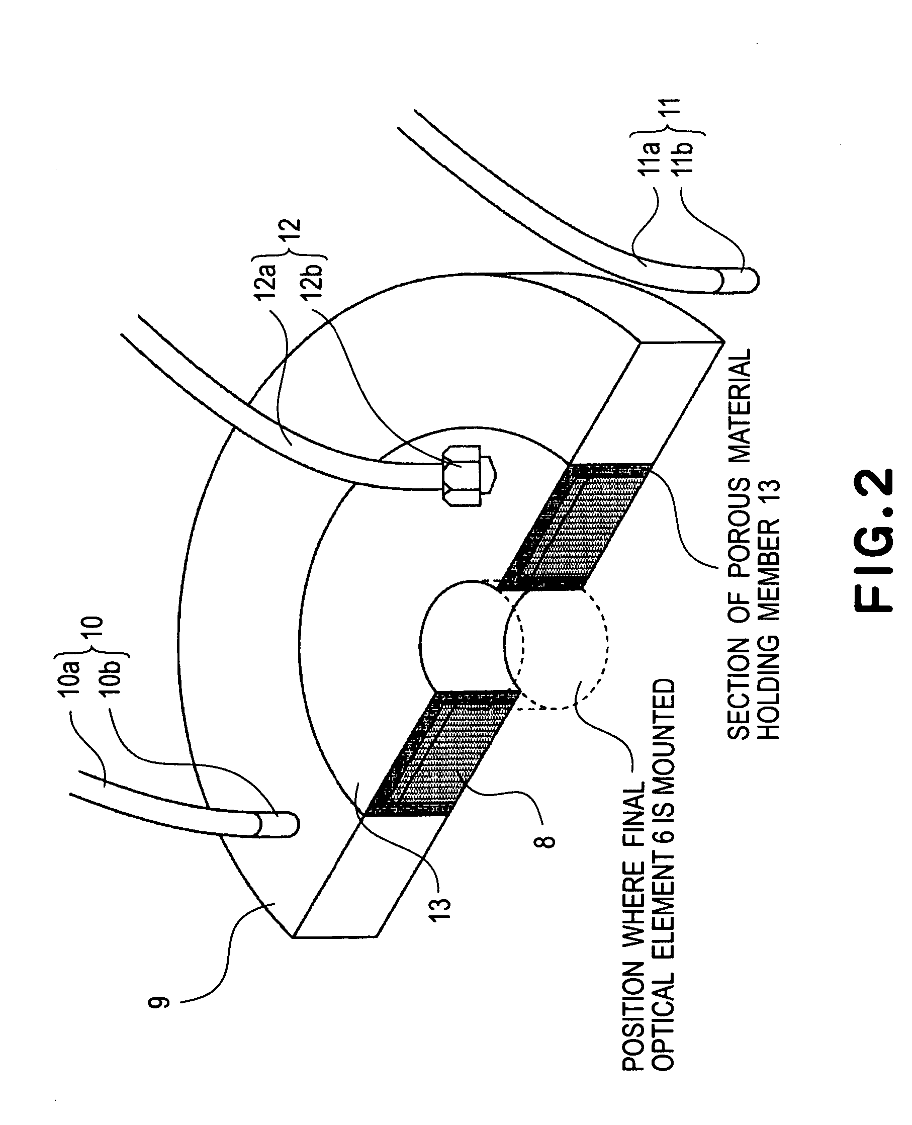
[0048]FIG. 5 illustrates the structure around a first porous material in a liquid immersion type exposure apparatus according to a further embodiment of the present invention.

[0049]The first and second embodiments have been described with reference to examples wherein a plurality of porous materials are used to perform liquid supply, liquid collection and removal of bubbles mixed in the liquid 7. In the third embodiment, a first porous material 8 is used as the porosity member and, by using nozzles mounted around it, liquid is supplied and collected. Description of similar structure and function of this embodiment, like those of the first or second embodiment, will be omitted to avoid duplication.

[0050]The first porous material 8 is hold within a porous-material holding member 13. Outside the porous-material holding member 13, there is a vacuum evacuation system 12 so that any bubbles mixed into the liquid 17 can be removed through the vacuum evacuation system 12. Also...


PUM

PropertyMeasurementUnit
liquid absorbing propertyaaaaaaaaaa
liquidaaaaaaaaaa
movement speedaaaaaaaaaa

Abstract

Disclosed is an exposure apparatus which includes a projection optical system for projecting a pattern of a reticle onto a substrate, wherein the substrate is exposed through a liquid medium kept at least in a portion between the substrate and an optical element of the projection optical system which optical element is nearest to the substrate, a supplying system for supplying a liquid medium, a collecting system for collecting a liquid medium, and an exhausting system for removing a bubble in the liquid medium through a bubble removing material having such property that it passes a gas but it does not pass a liquid.

Description

FIELD OF THE INVENTION AND RELATED ART[0001]This invention relates to an exposure apparatus to be used in a lithographic process for manufacture of devices such as semiconductor integrated circuit, image pickup device (CCD), liquid crystal display device or thin film magnetic head, for example. More particularly, the invention concerns a liquid immersion type exposure apparatus in which a substrate is exposed through a liquid medium supplied into at least a portion between a projection optical system and the substrate.[0002]In liquid immersion type exposure apparatuses, a liquid medium is interposed between a substrate to be exposed and one of optical elements, constituting a projection optical system, which one is nearest to the substrate. Since the numerical aperture (NA) can be increased thereby, attainment of higher resolution is expected. In relation to such liquid immersion type exposure apparatus, a method in which a substrate to be exposed as a whole is immersed in a liquid,...

Claims


Application Information

Patent Timeline
Patent Type & Authority Patents(United States)
IPC IPC(8): G03B27/42G03B27/52B05D5/00G03F7/20H01L21/027
CPCG03F7/70341
Inventor TOKITA, TOSHINOBU
Owner CANON KK
Why Eureka
Try Eureka