
Universal device for reducing electrolyte migration of flow battery

A liquid flow battery and electrolyte technology, applied in fuel cells, electrolyte flow processing, fuel cell additives, etc., can solve problems such as positive and negative electrolyte valence imbalance, electrolyte migration, etc., to solve capacity decay and easy operation , long-term operation and efficient effect

Inactive Publication Date: 2021-06-25
DALIAN INST OF CHEM PHYSICS CHINESE ACAD OF SCI
View PDF5 Cites 0 Cited by
  • Summary
  • Abstract
  • Description
  • Claims
  • Application Information

AI Technical Summary

Problems solved by technology

[0003] Different flow battery systems have different reasons for electrolyte migration. For example, in all-vanadium redox flow batteries, the migration rates of vanadium ions in different valence states are different, and because the number of hydrated ions carried by vanadium ions in different valence states is different, resulting in long-term operation. During the process, the valence state of the positive and negative electrolytes is out of balance, and the electrolyte has a small amount of migration

Method used


Image

  • Universal device for reducing electrolyte migration of flow battery

Examples


Embodiment 1

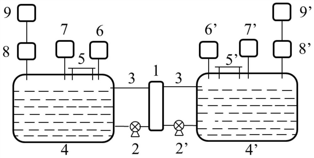
[0027] Taking the all-vanadium redox flow battery system as an example, assemble a 10-cell stack, in which the electrode is carbon felt, the electrode area is 1000cm2, the diaphragm is Nafion115, the volume of the positive and negative electrolytes is 30L, and the volumes of the positive and negative storage tanks are respectively 50L. Through the gas pressure regulator, the pressure in the positive storage tank is increased to 0.12MPa, the pressure in the negative storage tank is maintained at normal atmospheric pressure, the battery voltage window is 10V-15.5V, and the stack is charged and discharged at 100mA / cm2, and the cycle is 100 times Afterwards, the volume of the positive electrode electrolyte becomes 31L, the volume of the negative electrode electrolyte becomes 29L, and the battery capacity decays by 20%.

Embodiment 2

[0029] Taking the all-vanadium redox flow battery system as an example, assemble a 10-cell stack, in which the electrode is carbon felt, the electrode area is 1000cm2, the diaphragm is Nafion115, the volume of the positive and negative electrolytes is 30L, and the volumes of the positive and negative storage tanks are respectively 50L. Through the gas pressure regulator, the pressure in the negative storage tank is reduced to 0.8 atmospheric pressure, the pressure in the positive storage tank is maintained at normal atmospheric pressure, the battery voltage window is 10V-15.5V, and the stack is charged and discharged at 100mA / cm2, and the cycle is 100 times After that, the positive electrode electrolyte volume becomes 31.1L, the negative electrode electrolyte volume becomes 28.9L, and the battery capacity decays by 21%.

Embodiment 3

[0033] Taking the zinc-iron flow battery system as an example, assemble a 10-cell stack, in which the electrodes are carbon felts, the electrode area is 1000cm2, the diaphragm is PBI ion exchange membrane, the positive and negative electrolyte volumes are 30L, and the positive and negative storage tanks are The volume is 60L respectively. Through the gas pressure regulator, increase the pressure in the negative storage tank to 0.15MPa, keep the pressure in the positive storage tank at normal atmospheric pressure, charge the stack at 40mA / cm2 for 1h, discharge the stack at 40mA / cm2 for 1h, and cycle 50 times Afterwards, the volume of the positive electrode electrolyte solution becomes 25L, and the volume of the negative electrode electrolyte solution becomes 35L.


PUM

PropertyMeasurementUnit
areaaaaaaaaaaa
volumeaaaaaaaaaa
volumeaaaaaaaaaa

Abstract

The invention belongs to the field of flow battery application and energy recovery and relates to a device for reducing electrolyte migration of a flow battery, and aims to solve the problems of electrolyte migration, capacity fading and the like of an existing flow battery. According to the device, the pressures in storage tanks on the two sides are different by adjusting the pressures in electrolyte storage tanks on the two sides of a positive electrode and the negative electrode, and the migration of the electrolyte of the flow battery is reduced through the pressure difference by means of a physical mode. The migration of the electrolyte of the flow battery is reduced by adjusting the pressure in the electrolyte storage tanks on the two sides of the positive electrode and the negative electrode, meanwhile, the problems of capacity fading and the like caused by the migration of the electrolyte can be solved, and long-term operation of the battery and efficient utilization of the electrolyte are realized. The device is simple in process, simple and convenient to operate, low in cost and remarkable in effect, and does not need to use any additional chemicals.

Description

technical field [0001] The invention relates to the fields of application and energy recovery of a flow battery, in particular to a device for reducing electrolyte migration of a flow battery. Background technique [0002] Liquid flow battery is a new type of energy storage system. Compared with traditional energy storage methods, it has high energy conversion efficiency, flexible system design, large storage capacity, free location selection, deep discharge, safety and environmental protection, and low maintenance costs. It can be widely used in wind energy, solar energy and other renewable energy generation and energy storage, emergency power system, backup power station and power system peak shaving and valley filling, etc. It has outstanding advantages in energy storage, especially the fixed storage of renewable energy. The positive and negative electrolyte of the battery is an important part of the flow energy storage battery. It plays the role of storing energy, conduc...

Claims


Application Information

Patent Timeline
Patent Type & Authority Applications(China)
IPC IPC(8): H01M8/18H01M8/04276
CPCH01M8/188H01M8/04276Y02E60/50
Inventor 孙佳伟李先锋史丁秦刘涛张华民
Owner DALIAN INST OF CHEM PHYSICS CHINESE ACAD OF SCI
Learn More