Drainage device

A technology of a liquid discharge device and a liquid discharge hole, which is applied to parts of pumping devices for elastic fluids, liquid variable displacement machines, liquid fuel engines, etc. Complicated problems, to achieve the effect of smooth movement, wide applicability and simple structure

Active Publication Date: 2017-01-04
FU DING ELECTRONICSAL TECH JIASHAN +2
View PDF5 Cites 0 Cited by
  • Summary
  • Abstract
  • Description
  • Claims
  • Application Information

AI Technical Summary

Problems solved by technology

Because the general water pump or oil pump uses a motor to drive the pump body, its noise and vibration are relatively large during operation, and its volume is large and its structure is complex. When it is used to drain liquid in a vacuum environment, it is difficult to seal.
Therefore, the use of water pumps and oil pumps for liquid drainage is not widely applicable.

Method used


Image

  • Drainage device
  • Drainage device
  • Drainage device

Examples


Embodiment Construction

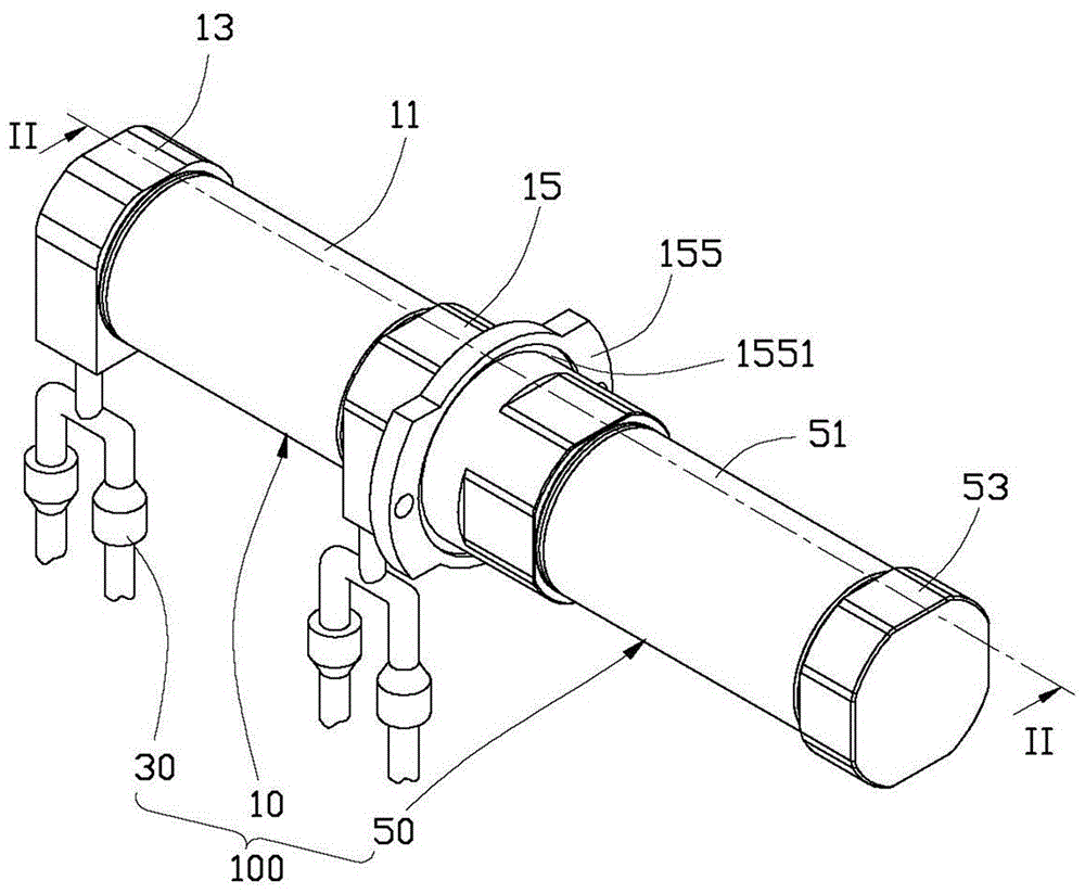
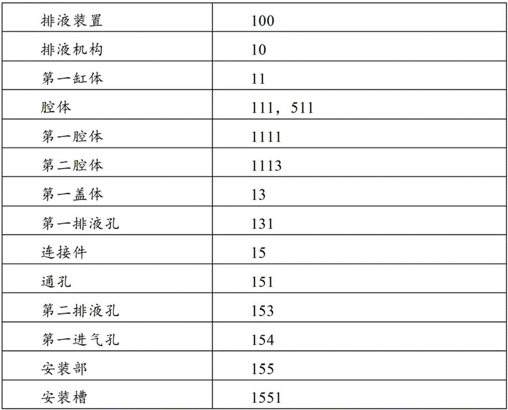
[0012] see figure 1 , the liquid discharge device 100 provided by the embodiment of the present invention is used to discharge liquid (such as water, solution, oil, etc.) from a container (not shown in the figure), and is especially suitable for liquid discharge in a vacuum environment. The liquid discharge device 100 includes a liquid discharge mechanism 10 , a liquid discharge pipe 30 connected to the liquid discharge mechanism 10 , and a driving mechanism 50 . The driving mechanism 50 can drive the liquid discharge mechanism 10 to discharge the liquid from the container through the liquid discharge pipe 30 .

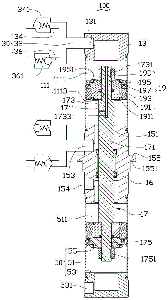
[0013] Please also refer to figure 2 , The liquid discharge mechanism 10 is designed in the form of a cylinder, which includes a first cylinder body 11 , a first cover body 13 , a connecting piece 15 , a sealing piece 16 , a piston rod 17 and a first piston assembly 19 . The first cover 13 and the connecting piece 15 are arranged on the opposite ends of the first c...


PUM


Abstract

A liquid discharge device, which includes a liquid discharge mechanism, two liquid discharge pipes and a driving mechanism. The liquid discharge mechanism includes a cylinder body, a first cover body, a connecting piece, a piston rod and a first piston assembly. There is a first cavity, the first cover and the connecting piece are respectively arranged at opposite ends of the cylinder body, the piston rod is movably passed through the connecting piece and accommodated in the cavity, and the piston assembly is arranged in the piston rod to accommodate At one end in the cavity, each discharge pipeline includes a first pipeline and a second pipeline communicated with the cavity, the first pipeline is provided with a first one-way valve, and the second pipeline is provided with a second pipeline. The one-way valve makes the flow direction of the liquid in the first pipeline and the second pipeline opposite. The connecting piece is provided with a mounting part to install the liquid discharge mechanism in the workplace. The driving mechanism is arranged on the connecting piece and Can drive the piston rod to move. The liquid discharge device moves smoothly and has wide applicability.

Description

technical field [0001] The invention relates to a liquid discharge device, in particular to a liquid discharge device which can be applied in a vacuum environment. Background technique [0002] Usually, people use liquid discharge devices such as water pumps and oil pumps to discharge liquid from the container. Because the general water pump or oil pump uses a motor to drive the pump body, the noise and vibration are relatively large during operation, and its volume is large and the structure is complex. When it is used to drain liquid in a vacuum environment, it is difficult to seal. Therefore, adopt water pump, oil pump to discharge liquid, its applicability is not wide. Contents of the invention [0003] In view of the above circumstances, it is necessary to provide a liquid discharge device with wide applicability. [0004] A liquid discharge device, which includes a liquid discharge mechanism, a liquid discharge pipeline connected with the liquid discharge mechanism...

Claims


Application Information

Patent Timeline
Patent Type & Authority Patents(China)
IPC IPC(8): F04B53/00
CPCF04B5/02F04B9/129
Inventor 张小龙
Owner FU DING ELECTRONICSAL TECH JIASHAN
Why Eureka
Try Eureka