Compressor oil injector having gas suction function

A technology of compressors and fuel injectors, which is applied in the direction of machines/engines, mechanical equipment, climate sustainability, etc., and can solve problems such as reducing compressor efficiency and liquid hammer loss

Active Publication Date: 2015-03-25
XI AN JIAOTONG UNIV
View PDF6 Cites 3 Cited by
  • Summary
  • Abstract
  • Description
  • Claims
  • Application Information

AI Technical Summary

Problems solved by technology

The higher pressure difference will cause the oil to maintain a high flow rate after being sprayed into the comp

Method used


Image

  • Compressor oil injector having gas suction function
  • Compressor oil injector having gas suction function
  • Compressor oil injector having gas suction function

Examples


Embodiment 1

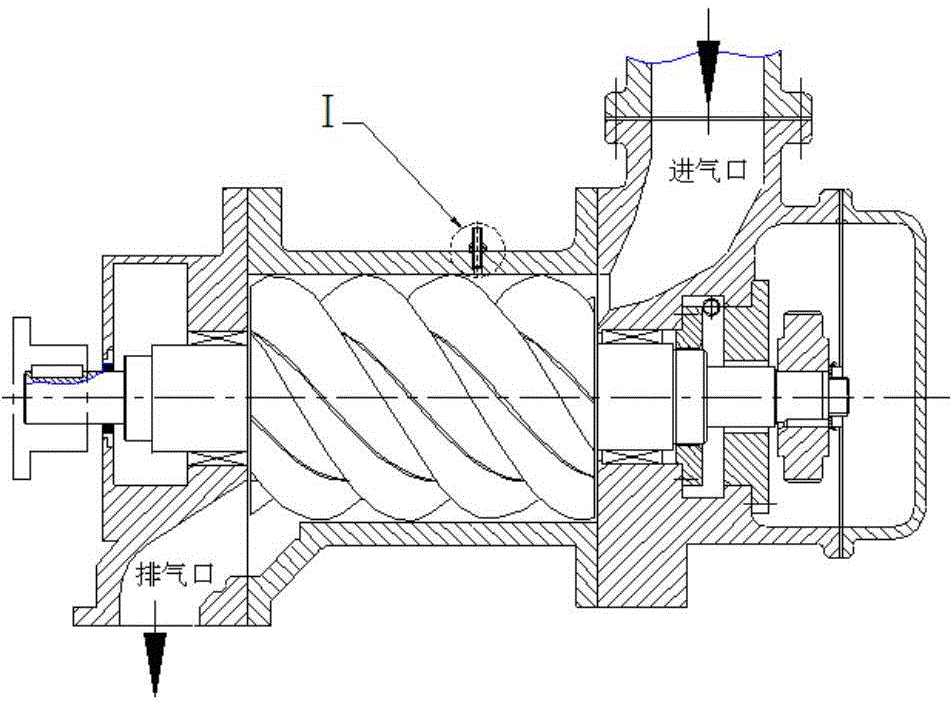
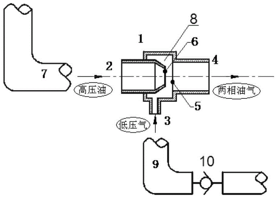
[0021] Install an injector 1 before the oil injection port of the rotary compressor, such as figure 1 As shown, the fuel injector includes a secondary nozzle 5 with a mixing chamber 8 at the rear end, a primary nozzle 6 set in the secondary nozzle mixing chamber 8, the rear end of the primary nozzle is an oil inlet 2, and the secondary nozzle The front end of the cylinder is an oil and gas outlet 4, which is connected to the oil injection port of the compressor. The cylinder wall of the secondary nozzle mixing chamber is provided with an air suction inlet 3 connected to a low-pressure air pipe 9 . The oil inlet 2 is connected to the high-pressure oil pipe 7, and the high-pressure oil cooled by the oil cooler is introduced from the oil inlet 2, and sprayed from the first-stage nozzle 6 into the second-stage nozzle 5. At this time, the suction inlet 3 sucks the low-pressure air into the mixing chamber 8 , mixed with high-pressure oil, sprayed into the compression chamber of the...

Embodiment 2

[0026] refer to Figure 5 , the secondary nozzle 5 of the injector 1 is set on the casing 11 of the compressor, and is integrated with the compressor casing 11, the mixing chamber 8 of the secondary nozzle is connected to the primary nozzle 6, and the pipe wall of the primary nozzle An air suction pipe 13 parallel to the axis of the nozzle is provided on the top, which communicates the mixing chamber with the air suction inlet 3, and the air suction inlet communicates with the air inlet of the compressor or with the atmosphere. After the high-pressure oil enters the mixing chamber 8 through the inlet 2 of the primary nozzle, the gas is inhaled from the suction pipe 13 through the suction inlet. into the compression chamber of the compressor.

[0027] The characteristic of this embodiment is that the suction pipe 13 is directly arranged on the primary nozzle 6 .

Embodiment 3

[0029] refer to Figure 5 , this embodiment is basically the same as Embodiment 2, and the feature of this embodiment is that the suction pipe 13 is directly arranged on the compressor casing 11, parallel to the axial direction of the compressor, and connects the mixing chamber 8 to the suction of the compressor. The mouth is connected.


PUM


Abstract

The invention discloses a compressor oil injector having a gas suction function. The compressor oil injector is characterized by comprising a first-stage nozzle, a second-stage nozzle and a low-pressure gas suction inlet, wherein a cavity is formed between the first-stage nozzle and the second-stage nozzle and is communicated with the low-pressure gas suction inlet. High-pressure oil is injected in from the first-stage nozzle, then gas is sucked in from the low-pressure gas suction inlet, and a two-phase oil and gas mixture is formed, injected into the second-stage nozzle and finally injected into a compression cavity. The function of gas suction of the compression cavity is realized, and the efficiency of a compressor is increased.

Description

technical field [0001] The invention relates to an oil injection device in a compressor. Background technique [0002] Compressors are widely used in railways, ships, mines, construction, chemicals, textiles, metallurgical machinery, military instruments, ships and other industries. Compared with reciprocating piston compressors, rotary compressors have the advantages of simple structure, reliable operation, small size, light weight, and low noise. [0003] In order to ensure lubrication of moving parts, cooling of the rotor and compressed gas, it is necessary to spray oil into the compression cavity of the rotary compressor. The compressor discharges the oil-air mixture from the exhaust port, and then enters the oil-air separator for separation. After the oil is cooled by the cooler, it is sprayed into the compression chamber. After the oil sprayed into the compression chamber is fully in contact with the compressed gas, it can also absorb part of the compression heat, th...

Claims


Application Information

Patent Timeline
IPC IPC(8): F04C29/02
CPCY02P20/10
Inventor 侯方勇谢佳宋明毅李直吴伟烽
Owner XI AN JIAOTONG UNIV
Why Eureka
Try Eureka