Centrifugal fan and air-conditioning apparatus
A blower and space technology, applied in the direction of machines/engines, mechanical equipment, engine functions, etc., can solve the problems of reduced adhesion, damage, and reduced reliability of the cladding surface, and achieve the effect of suppressing deformation
- Summary
- Abstract
- Description
- Claims
- Application Information
AI Technical Summary
Problems solved by technology
Method used
Image

Examples
Embodiment approach 1
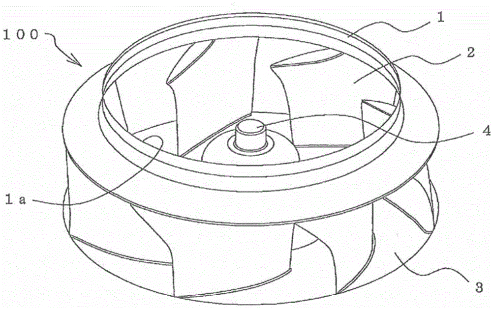
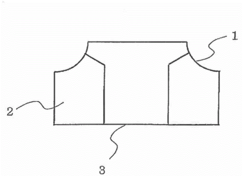
[0024] figure 1 It is a perspective view which shows the structure of the centrifugal blower which concerns on Embodiment 1 of this invention. in addition, figure 2 It is a figure which shows the schematic structure of the cross section of the impeller of the centrifugal blower concerning Embodiment 1 of this invention. Such as figure 1 as well as figure 2 As shown, the impeller 100 of the centrifugal fan in Embodiment 1 is provided with a plurality of ( figure 1 7 in the middle) blade 2.
[0025] The shroud 1 is in the shape of a bell mouth and has an air inlet 1a. In addition, the blade 2 of the present embodiment is a three-dimensional blade having a twisted shape between the shroud 1 and the main plate 3 . Therefore, reduction in noise, reduction in power consumption, and the like can be achieved. In addition, a boss 4 serving as a rotation shaft is attached to the center of the main plate 3 . A driving device (fan motor, etc.) is attached to the sleeve 4 to r...
Embodiment approach 2
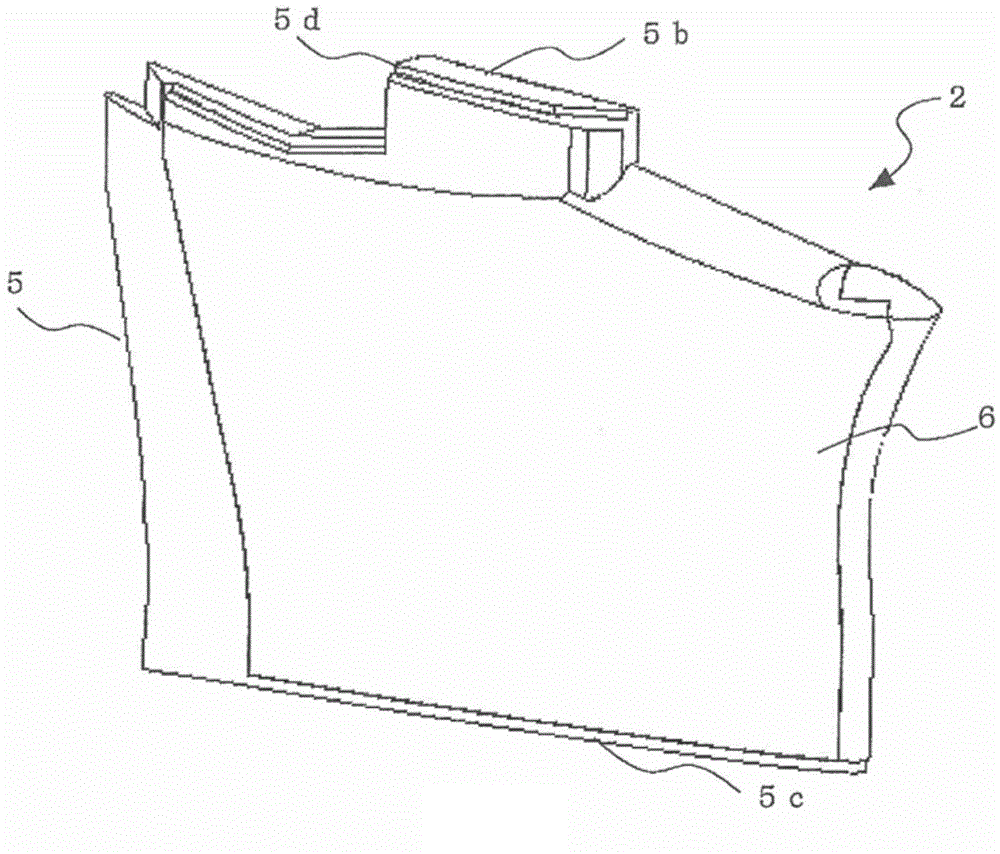
[0036] Figure 7 It is a perspective view which shows the structure of the main blade of the centrifugal blower concerning Embodiment 2 of this invention. exist Figure 7 In , components having the same functions as those described in Embodiment 1 above are denoted with Image 6 etc. with the same reference numerals. For example, in the above-mentioned embodiment, ribs 10 are added for reinforcement so as to be able to withstand external pressure (especially pressure during welding). Here, since the weight of the blade 2 and thus the impeller 100 is increased by the rib 10, it is preferable that the weight of the rib 10 be as light as possible. Therefore, in the impeller 100 of the centrifugal blower of this embodiment, under the premise of ensuring the function as the rib 10, the height of the rib 10 is formed differently (partially formed lower), so as to realize the light weight of the impeller 100. change.
[0037] In addition, as described in Embodiment 1, if the rib...
Embodiment approach 3
[0040] Figure 8 It is a perspective view which shows the structure of the main blade of the centrifugal blower concerning Embodiment 3 of this invention. exist Figure 8 In , components having the same functions as those described in Embodiment 1 above are denoted with Image 6 etc. with the same reference numerals. In the second embodiment described above, weight reduction is achieved by forming the ribs 10 with different heights. In particular, it is formed so that the area of the rib 10 formed on the back side of the side surface 5c on the main board side is as small as possible, so that sink marks generated during welding can be reduced.
[0041] In the impeller 100 of the centrifugal blower according to the present embodiment, the weight of the impeller 100 can be reduced by making the thickness of the rib 10 different (in particular, forming a part thinner) while ensuring the function as the rib 10. . At this time, for example Figure 8 As shown, by forming the ...
PUM
 Abstract
Description
Claims
Application Information
PatSnap Eureka turns technology decisions into work you can execute. Powered by our Innovation Knowledge Graph, it runs expert workflows across engineering, life sciences, materials and intellectual property. Get your review-ready output in minutes.


