Hook rod gear mechanism for parallel shaft transmission

A gear mechanism, parallel shaft technology, applied in the direction of transmission, gear transmission, belt/chain/gear, etc., can solve the problem that the parallel shaft transmission mode of mechanical transmission cannot be realized, and the movement and power transmission of two parallel shafts in the plane cannot be realized. , use scope restrictions, etc.

Inactive Publication Date: 2015-03-25
CHINA UNIV OF GEOSCIENCES (WUHAN)
View PDF4 Cites 15 Cited by
  • Summary
  • Abstract
  • Description
  • Claims
  • Application Information

AI Technical Summary

Problems solved by technology

The biggest limitation of the above two transmission mechanisms is that they can only realize the motion and power transmission between plane cross axes, but cannot realize the motion and power transmission between two parallel axes in the plane
Therefore, their scope of use is greatly limited, and the most widely used parallel shaft transmission method in mechanical transmission cannot be realized.

Method used


Image

  • Hook rod gear mechanism for parallel shaft transmission
  • Hook rod gear mechanism for parallel shaft transmission
  • Hook rod gear mechanism for parallel shaft transmission

Examples


Embodiment 1

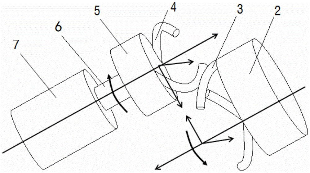
[0050] Embodiment 1: The present invention provides a hook gear mechanism for parallel shaft transmission, which adopts a parallel shaft external meshing transmission mode, such as figure 1 As shown, including driving wheel 5 and driven wheel 2, driving wheel 5 and driven wheel 2 form a pair of transmission pairs, driving wheel 5 is connected to input shaft 6, driven wheel 2 is connected to output shaft, that is, driven wheel 2 is connected to the driven wheel through the output shaft The loads are connected; the axes of the driving wheel 5 and the driven wheel 2 are parallel to each other.

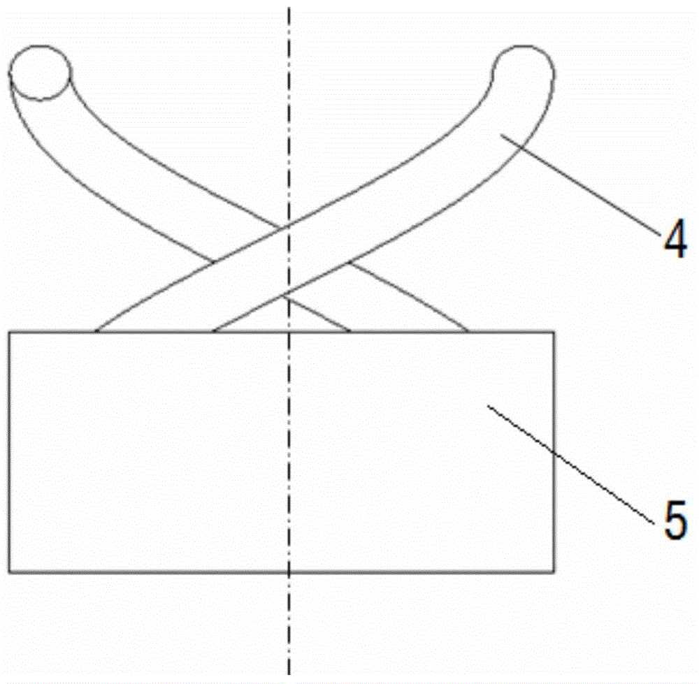
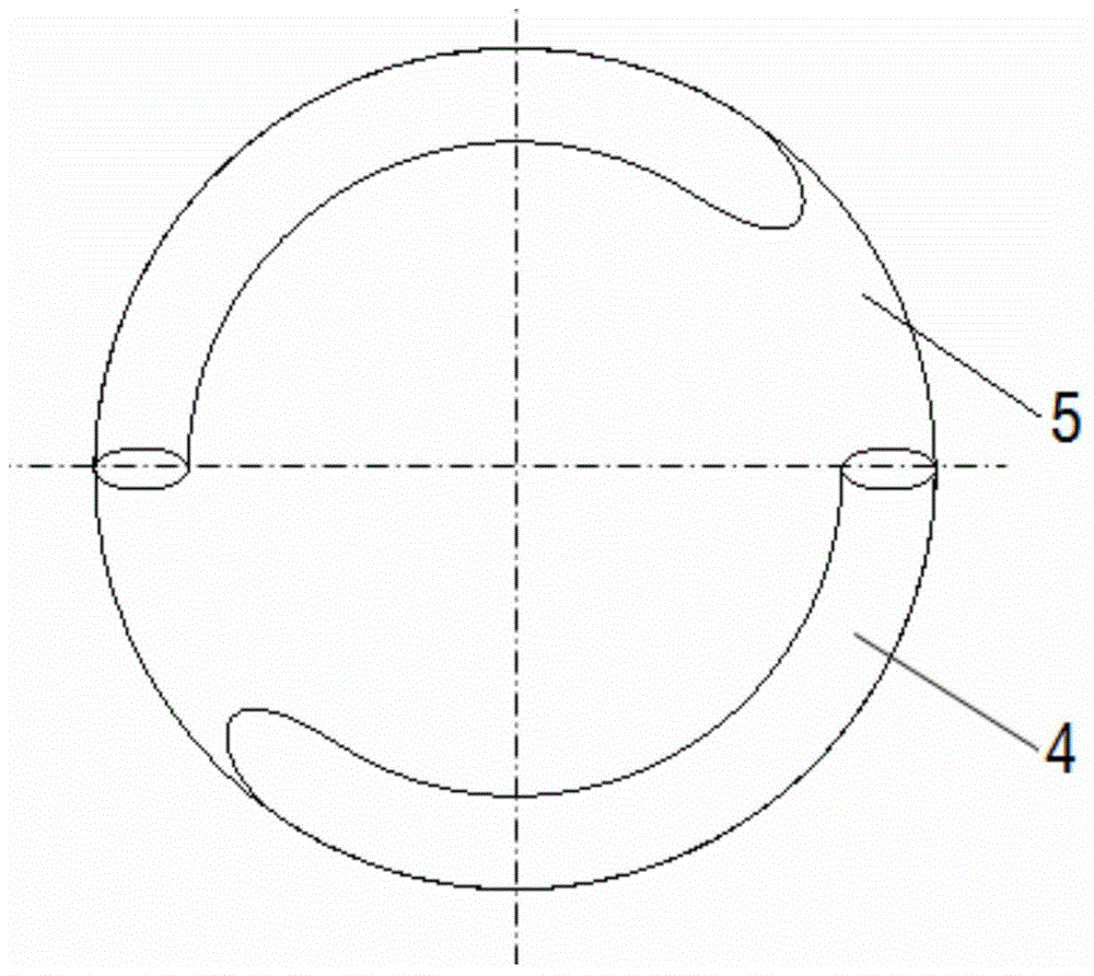
[0051] see figure 2 , 3 , 4, the driving wheel 5 is provided with a driving hook 4, the driven wheel 2 is provided with a driven hook 3, the driving hook 4 and the driven hook 3 have the same diameter, and the driving hook 4 is evenly distributed on the driving wheel 5. In the circumference on the end surface of the cylinder, the driven hook 3 is also evenly distributed on the circumfe...

Embodiment 2

[0077] Embodiment 2: A hook gear mechanism for parallel shaft transmission of the present invention is applied to a reducer in which the input shaft and the output shaft rotate in the same direction using the parallel shaft internal meshing transmission mode. Such as Figure 7 As shown, when in use, the angular velocity vector angle θ=0° of the main and driven wheels, the rotation direction of the input shaft 1 and the output shaft 6 are the same, the driving wheel 5 is installed on the input shaft 6 of the driver 7, and the driven wheel 2 is installed on the output shaft 6. on axis 1. At this time, the axial distance between the input shaft 1 and the output shaft 6 is the helical radius of the driven hook lever minus the helical radius of the driving hook lever. There are two driving hook bars 4 on the driving wheel 5 described in this embodiment, and three driven hook bars 3 are arranged on the driven wheel 2. When the driver 7 drives the driving wheel 5 to rotate, because ...

Embodiment 3

[0082] Embodiment 3: A hook gear mechanism for parallel shaft transmission according to the present invention is applied to a reducer in which the input shaft and the output shaft rotate in the same direction using the parallel shaft internal meshing transmission mode. its structure and Figure 7 are basically the same, the only difference is that the number of active hook levers is 1, the number of driven wheel hook levers is 8, m=3mm, n=2mm, transmission ratio i 12=8, the interaxial distance a=21mm, the diameter D of the driving and driven hook rods is 2mm, it can be calculated that the diameter of the driving wheel cylinder in this embodiment is 8mm, and the diameter of the driven wheel cylinder is 50mm.

[0083] A hook gear mechanism for parallel shaft transmission of the present invention can be used in micro-machines and micro-mechanical devices to provide a mechanism for continuous and stable meshing transmission between two parallel shafts in a plane and a transmission...


PUM


Abstract

The invention relates to a hook rod gear mechanism for parallel shaft transmission. The hook rod gear mechanism comprises a transmission pair composed of a driving wheel and a driven wheel. The axis of the driving wheel and the axis of the driven wheel are parallel to each other. The driving wheel is connected with an input shaft. The driven wheel is connected with an output shaft. Driving hook rods on the driving wheel are evenly distributed in the circumference of the cylindrical end face of the driving wheel. Driven hook rods on the driven wheel are also evenly distributed in the circumference of the cylindrical end face of the driven wheel. The driving hook rods and the driven hook rods are each in a cylindrical spiral linear shape. When the driving wheel and the driven wheel are installed, the driving hook rod and the driven hook rod in one pair are meshed, the driving wheel is driven by a driver to rotate, the continuous and stable meshing is completed through the meshed hook rods, and transmission between the two parallel shafts is achieved. The spiral linear shapes of the driving hook rods and the driven hook rods can be determined according to the installation spatial coordinate system, the transmission ratio and other parameters of the driving wheel and the driven wheel and according to the hook rod contact line equation. The hook rod gear mechanism is simple in structure, fewer in transmission mechanism part, small in size, light in weight, large in transmission ratio, stable in transmission and suitable for being applied to the fields of mini machines and micro machines.

Description

technical field [0001] The invention relates to a hook gear mechanism for parallel shaft transmission, in particular to a space curve meshing transmission mechanism for parallel shaft transmission. Background technique [0002] The development of modern science and technology has promoted the rapid development of 1-100mm micro-mechanical devices and 10μm-1mm micro-mechanical devices. Micro-mechanics has become one of the frontiers of mechanical disciplines. Research has become one of the important directions in the frontier research field of mechanical science. One of the core functions of micromachines and micromachines is to realize small power and continuous motion transmission in a small space. [0003] So far, researchers from various countries have continuously innovated in the design and manufacture of gear transmission mechanisms, and have successively carried out research on micro transmission mechanisms and drive technology, and have made great achievements. Gene...

Claims


Application Information

Patent Timeline
Patent Type & Authority Applications(China)
IPC IPC(8): F16H1/06F16H1/22
CPCF16H1/06F16H1/22
Inventor 陈祯李波张萌赵权杨静
Owner CHINA UNIV OF GEOSCIENCES (WUHAN)
Why Eureka
Try Eureka