Spiral lifting mechanism

A technology of spiral lifting and lifting screw, which is applied in the direction of mechanical equipment, belts/chains/gears, transmission devices, etc., to achieve the effect of reducing clearance, low cost and eliminating clearance

Active Publication Date: 2015-03-25
北京兴华机械厂有限公司
View PDF4 Cites 3 Cited by
  • Summary
  • Abstract
  • Description
  • Claims
  • Application Information

AI Technical Summary

Problems solved by technology

However, these gaps are unacceptable, or a fatal shortcoming, for precision transmission mechanisms with higher requirements

Method used


Image

  • Spiral lifting mechanism
  • Spiral lifting mechanism
  • Spiral lifting mechanism

Examples


Embodiment Construction

[0027] The precision screw lifting mechanism according to the present invention will be further described in detail with reference to the accompanying drawings and specific embodiments.

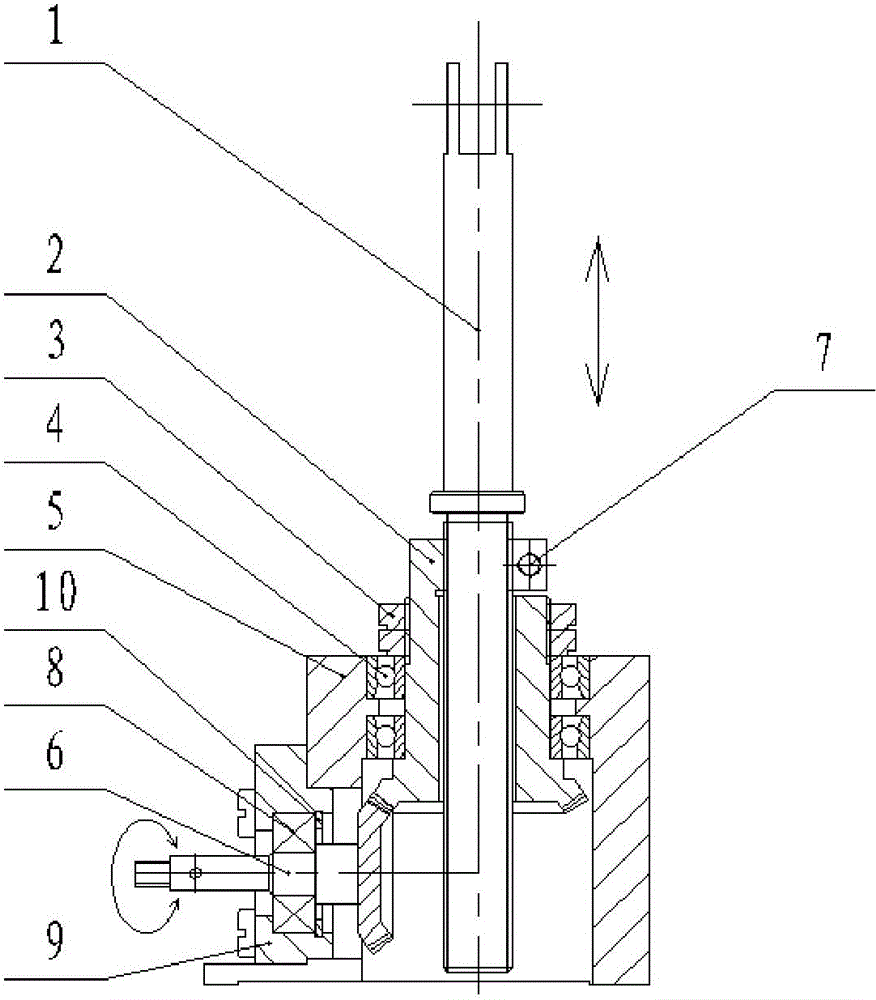
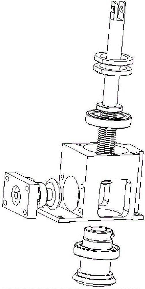
[0028] Such as Figure 2-Figure 7 As shown, the screw lifting mechanism of the present invention includes a lifting screw 1, a gear screw nut 2, two lock nuts 3, two angular contact ball bearings 4, a machine base 5, a transmission gear member 6, an adjustment screw 7, and a deep groove Ball bearing 8, end cover 9, and collar 10.

[0029] Such as Figure 7 As shown, the first end of the transmission gear member 6 has a rotating shaft 61 connected to an external driving device, the second end has a driving bevel gear 62 meshing with the gear nut 2 , and the middle of the transmission gear member has an annular step 63 .

[0030] Such as Figure 4a and Figure 4b As shown, the gear screw nut 2 is a cylindrical structure, and its middle part has a threaded hole 21 matched with the lifting sc...


PUM


Abstract

The invention discloses a spiral lifting mechanism which is applied to the industries of precise machines, automobiles, precise machine tools and the like. The set of precise spiral lifting mechanism is composed of a transmission bevel gear, a lifting lead screw, a gear nut, a machine base, bearings and other mechanical parts. The spiral lifting mechanism has the advantages of being compact in structure, low in part machining precision, simple in assembling method and capable of achieving accurate spiral lifting. In addition, the spiral lifting mechanism is low in machining cost, capable of being applied to multiple precise machine industries and convenient to apply and popularize.

Description

technical field [0001] The invention belongs to the field of precision mechanical transmission, and in particular relates to a spiral lifting mechanism used in industries such as aviation, aerospace, automobiles, and precision machine tools. Background technique [0002] In the currently commonly used lifting transmission mechanisms, mechanisms such as bearings and lead screws are often used. These structures have certain defects, and a small amount of clearance movement is likely to occur during the working process. These small clearance activities are acceptable for less demanding lifting transmission mechanisms. However, these gaps are unacceptable, or are fatal disadvantages, for high-precision transmission mechanisms. Contents of the invention [0003] The technical problem to be solved by the present invention is to propose a screw lifting mechanism to solve the gap problem in the screw transmission to a certain extent in view of the deficiencies of the prior art. ...

Claims


Application Information

Patent Timeline
Patent Type & Authority Applications(China)
IPC IPC(8): F16H37/02F16H25/24
CPCF16H25/2003F16H25/24F16H37/02
Inventor 韩雪涛廖世宾
Owner 北京兴华机械厂有限公司
Why Eureka
Try Eureka