Al technical title is built by PatSnap Al team. It summarizes the technical point description of the patent document.
A deluge alarm valve and valve body technology, applied in the direction of valve lift, valve details, valve devices, etc., can solve the problems of water and gas two-phase corrosion, affecting the normal service life of valves and pipe fittings, and the reciprocating oscillation of pipe network pressure, etc., to achieve The effect of preventing accidental opening of spraying and reducing the pressure oscillation of the pipe network
Inactive Publication Date: 2018-02-09
KUAIDA FIRE SCI & TECH
View PDF9 Cites 0 Cited by
Summary
Abstract
Description
Claims
Application Information
AI Technical Summary
This helps you quickly interpret patents by identifying the three key elements:
Problems solved by technology
Method used
Benefits of technology
Problems solved by technology
Usually, due to the existence of this part of the gas, the pressure of the pipe network will reciprocate and oscillate, and the two-phase corrosion of water and gas will affect the normal service life of the valve and pipe fittings;
Method used
Image
Click on the blue label to locate the original text in one second.
Reading with bidirectional positioning of images and text.
Examples
Embodiment Construction
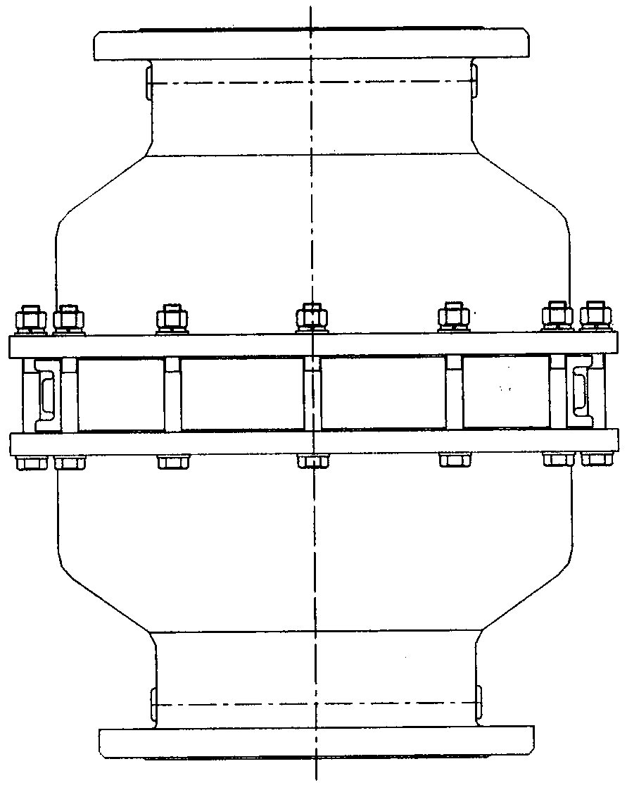
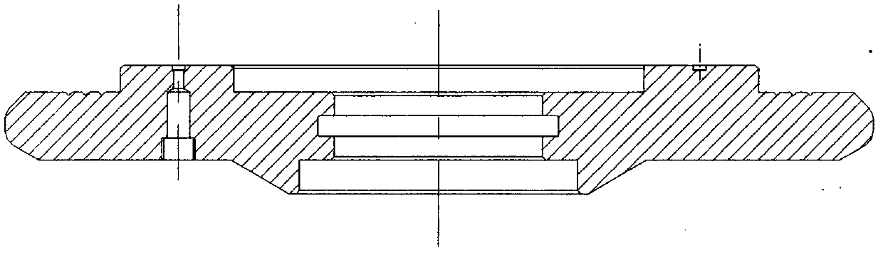
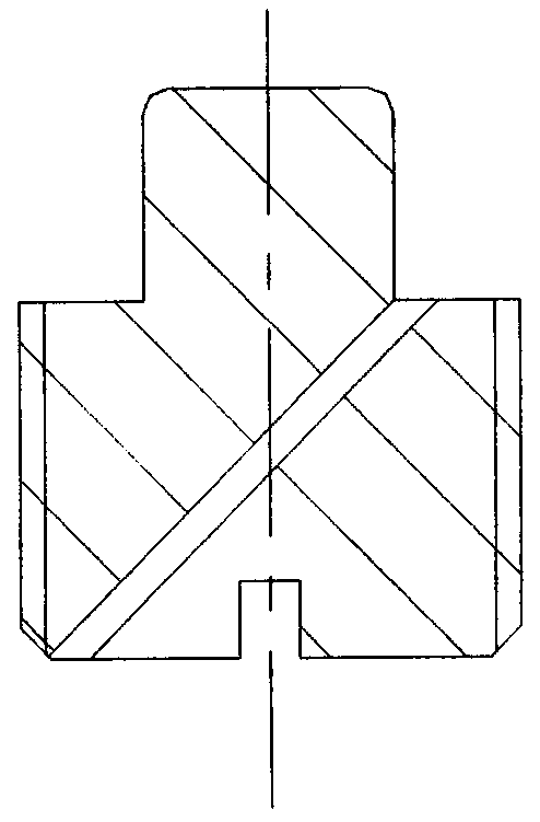
[0014] The middle valve body is fastened between the upper valve body and the lower valve body by bolts. The outer circle of the middle valve body is positioned and sealed by the O-rings on the upper and lower ends of the middle valve body. The valve seat is embedded in the middle valve body and sealed by the O-ring. It is fastened by several locking bolts; the sealing ring is clamped by the base plate and the pressure plate, and screwed on the upper side of the mandrel, and the floating ball is sealed in the hole of the base plate by a screw plug. The screw plug adopts a convex head screw structure, and is designed with a 45° exhaust hole, which leads to the screw plug shaft shoulder plane and the outer edge of the tail plane respectively; a straight groove is processed in the center of the tail; the 45° exhaust oblique hole avoids high-speed airflow The direct impact on the floating ball ensures the smoothness of the exhaust. The center of the bottom plate is designed with a...
PUM
Abstract
The invention discloses a drench alarm valve, and belongs to the field of firefighting and fire extinguishment. The drench alarm valve is in the shape of an imitated hammer, is of a single-piston reciprocating structure, is provided with a driving cavity and an air cavity, and has pressurized adverse water current driving starting and normal-pressure fair water current resetting action mechanisms. By the aid of the drench alarm valve, the problem of mistaken blowing accidents of conventional drench alarm valves can be solved, and air accumulated on a water source side of a sealing ring can be eliminated. The drench alarm valve comprises a valve seat, an upper valve body, a lower valve body, a bushing, a piston, a spring, a middle valve body, a mandrel, a bottom plate, the sealing ring, a pressure plate, floating balls and plug screws. The middle valve body is fastened in the upper valve body and the lower valve body, the main sealing ring is fixedly clamped by the bottom plate and the pressure plate and is screwed on the upper side of the mandrel, the floating balls are sealed in holes of the bottom plate by the plug screws, the spring is arranged between the middle valve body and the piston, and the piston is screwed at the lower end of the mandrel and is mounted in a piston cavity of the middle valve body. The drench alarm valve has the advantages that the drench alarm valve which is a starting valve can be opened when blowing is required, so that a pressure source can be led to the driving cavity, a sealing ring assembly can be started, and water outlet effects can be realized; the starting valve can be closed when stopping is required, so that the pressure of the driving cavity can be released, and the drench alarm device can be closed and sealed; the drench alarm valve has a broad application prospect in the fields of electric power, chemical engineering, metallurgy and tunnels.
Description
technical field [0001] The invention relates to a deluge alarm valve for water spraying fire extinguishing system, which allows water to flow into the system in one direction to perform fire extinguishing. The action mechanism of water flow-driven opening and normal pressure and water flow reset can remove the air accumulated on the water source side of the sealing ring in real time, and belongs to the field of fire fighting. Background technique [0002] The current national standard GB5135.3-2003 deluge alarm valve, when the pressure in the control chamber drops, the disc will open to discharge water. When the water source fluctuates, the deluge alarm valve is often washed away by the peak water shock, resulting in mis-discharge accidents. After the water supply system is overhauled and the water is cut off, it is necessary to go to the site to re-operate the deluge alarm valve to establish it. In large-scale areas such as metallurgy, electric power, chemical industry, tun...
Claims
Application Information
Patent Timeline
Application Date:The date an application was filed.
Publication Date:The date a patent or application was officially published.
First Publication Date:The earliest publication date of a patent with the same application number.
Issue Date:Publication date of the patent grant document.
PCT Entry Date:The Entry date of PCT National Phase.
Estimated Expiry Date:The statutory expiry date of a patent right according to the Patent Law, and it is the longest term of protection that the patent right can achieve without the termination of the patent right due to other reasons(Term extension factor has been taken into account ).
Invalid Date:Actual expiry date is based on effective date or publication date of legal transaction data of invalid patent.