Breast pump

a pump and breath technology, applied in the direction of machines/engines, mechanical equipment, positive displacement liquid engines, etc., can solve the problems of increasing reducing the pumping time, and unpleasant vibration of the person or animal to whom the pumping is applied, so as to reduce the amplitude reduce the transmission and reduce the noise of the pressure oscillation

Active Publication Date: 2018-09-06
KONINKLJIJKE PHILIPS NV
View PDF9 Cites 0 Cited by
  • Summary
  • Abstract
  • Description
  • Claims
  • Application Information

AI Technical Summary

Benefits of technology

The patent describes a pumping system that uses a flexible member to reduce pressure oscillations and make the pumping system more comfortable for the person using it. By bending the flexible member towards a lower pressure volume, the system achieves a decrease in pressure in that volume and an increase in pressure in the other volume. This reduces stress on the pump and prolongs its life, which is especially useful in hospitals where the equipment is expected to last many times longer than in other situations. Additionally, pumping the two volumes with different phases ensures that the flexible member does not bend too far and block the channel.

Problems solved by technology

In certain situations, such as with a breast-pump for expressing milk, the person or animal to whom the pumping is being applied may find the vibration unpleasant.
Also the oscillations of the pumping may create noise which can also be undesirable.
Increasing the stroke can reduce the pumping time but this increases the pressure oscillation amplitude.
Decreasing the stroke could reduce the pressure oscillation amplitude but would slow the pumping process.
This could be compensated by increasing the operating frequency of the pump i.e. reducing the pump cycle time but this can impose restrictions on the choice of the pump or on its operating life-time.

Method used


Image

  • Breast pump
  • Breast pump
  • Breast pump

Examples


Embodiment Construction

[0054]In the following description, like references designate like elements. Furthermore, in the interests of brevity, features will only be described once except and where appropriate. The embodiments described herein are given purely as examples and without limitation. The reference signs are purely for illustration and are not limiting wherever used, including in the claims.

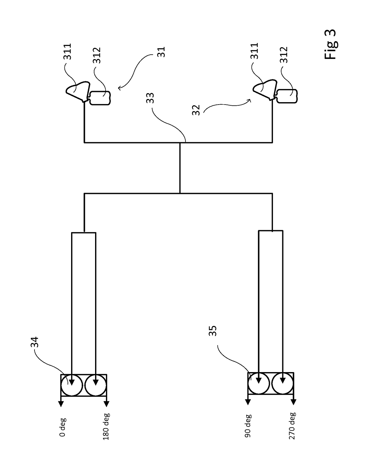
[0055]FIG. 3 represents a possible way of reducing the amplitude of pressure oscillations whilst still achieving an acceptably quick overall pumping operation. Two fluid extraction units such as milk expression units 31, 32 are connected by a network of tubes 33 to a pair of two-headed pumps 34, 35 such that each milk expression unit 31, 32 is connected to both of the two-headed pumps 34, 35. Each of the milk expression units has a cup 311 which is applied to the breast and, preferably, a container 312 for receiving the milk. The pair of two-headed pumps are controlled such that their phases are offset by 90°....


PUM


Abstract

There is provided a pressure oscillation damper in order to reduce the level of the pressure oscillations by the use of for a fluid extraction system. The pressure oscillation damper comprises a wall enclosing a main volume, at least two inlets, arranged in the wall and adapted to be connected to fluid extraction units, at least two outlets, arranged in the wall and adapted to be connected to pumping units, and at least one flexible member, arranged in the first volume so as to divide the first volume into at least two secondary volumes, each secondary volume forming a channel between the at least one inlet and at least one outlet, the flexible member being configured to bend toward a secondary volume having a lower pressure.

Description

FIELD OF THE INVENTION[0001]The invention relates pumping systems for extracting fluids, and in particular those for extracting milk from mammary glands such as women's breasts.BACKGROUND OF THE INVENTION[0002]Pumps used for pumping a fluid (a gas or a liquid) are often mechanical. They have a period (inlet stroke) which is when they draw the fluid into a chamber and a period (exhaust stroke) which is where the inlet is closed off and the contents of the chamber are forced out of an outlet. The total of these two periods will be called, for convenience, the pump cycle time here. Drawing the fluid in is achieved by drawing back a piston or a membrane so as to increase the volume in the chamber and forcing is out is by reversing the action so as to decrease the volume of the chamber. The displacement of the membrane or piston is also called the stroke. Changing the degree of displacement is called changing the stroke.[0003]The pumps often used for milk expression are membrane pumps. I...

Claims


Application Information

Patent Timeline
Patent Type & Authority Applications(United States)
IPC IPC(8): A61M1/06A61M1/00F04B11/00F16L55/04
CPCF16L55/04F04B11/0033A61M2202/04A61M1/0037A61M1/062A61M1/06F04B11/0016F04B11/005A61M1/74A61M1/75A61M1/82
Inventor VAN WIERINGEN, ARJAN TEODORAALDERS, ARNOLD
Owner KONINKLJIJKE PHILIPS NV
Why Eureka
Try Eureka