Backlight source and display device

A technology of backlight source and back plate, applied in the field of display device and backlight source, can solve problems such as deformation, collision between diaphragm and fixed column, and achieve the effect of reducing friction and deformation.

Inactive Publication Date: 2015-03-25
HEFEI XINSHENG OPTOELECTRONICS TECH CO LTD +1
View PDF6 Cites 14 Cited by
  • Summary
  • Abstract
  • Description
  • Claims
  • Application Information

AI Technical Summary

Problems solved by technology

However, high-temperature and high-humidity tests are required in the production process of liquid crystal displays. During the test process, the optical film, light guide plate and reflector are prone to expand an

Method used


Image

  • Backlight source and display device
  • Backlight source and display device
  • Backlight source and display device

Examples


Embodiment Construction

[0023] Specific embodiments of the present invention will be described in detail below in conjunction with the accompanying drawings. It should be understood that the specific embodiments described here are only used to illustrate and explain the present invention, and are not intended to limit the present invention.

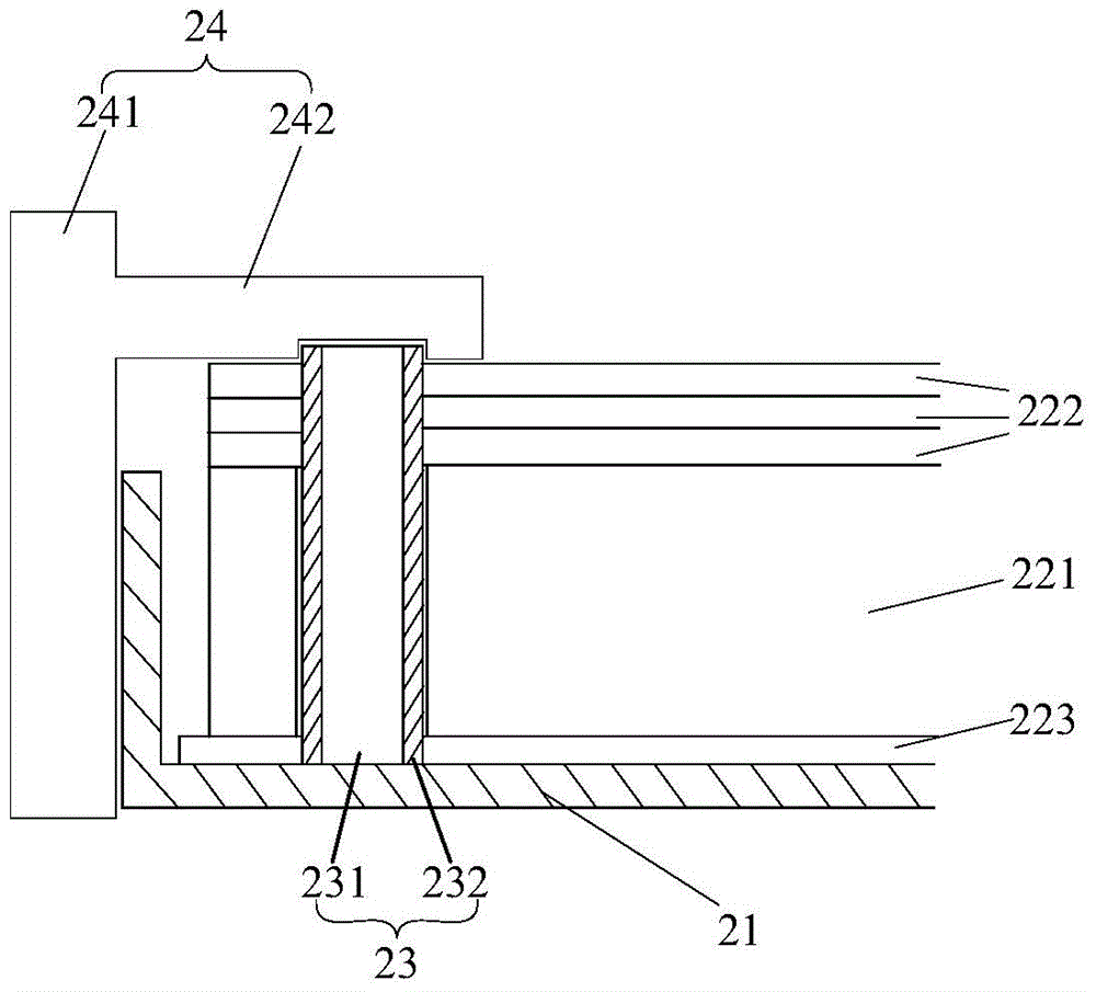
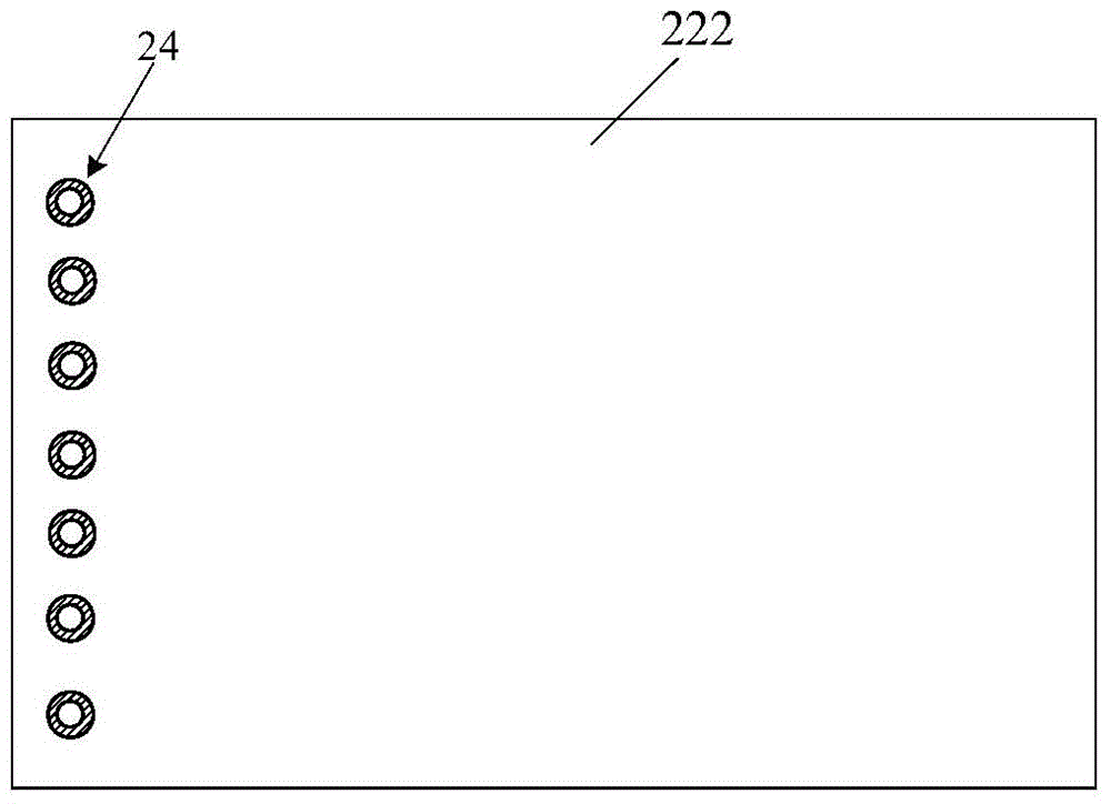
[0024] As a first aspect of the present invention, a backlight is provided, such as figure 2 As shown, it includes a back plate 21, a reflective sheet 223 arranged in the back plate 21, a light guide plate 221 arranged above the reflective sheet 223, a plurality of optical films 222 arranged above the light guide plate 221, a reflective sheet 223, a guide plate At least one through hole is provided on the edge area of ​​the light plate 221 and the optical film 222, which simultaneously passes through the reflective sheet 223, the light guide plate 221 and the optical film 222, and the back plate 21 is provided with a positioning post 23 passing through the thro...


PUM


Abstract

The invention provides a backlight source. The backlight source comprises a back board, a reflecting sheet arranged in the back board, a light guide board arranged above the reflecting sheet, and a plurality of optical membranes arranged above the light guide board. At least one through hole penetrating through the reflecting sheet, the light guide board and the optical membranes at the same time is formed in edge areas of the reflecting sheet, the light guide board and the optical membranes. The back board is provided with positioning columns penetrating through the through holes. Each positioning column comprises a positioning column body and an elastic material layer arranged on the side face of the positioning column body. Correspondingly, the invention further provides a display device. According to the backlight source and the display device, the possibility of deformation of the light guide board, the optical membranes and the reflecting sheet can be reduced in the high-temperature and high-humidity test.

Description

technical field [0001] The invention relates to the field of display technology, in particular to a backlight source and a display device including the backlight source. Background technique [0002] The liquid crystal display includes a display panel and a backlight. The backlight includes a reflector, a light guide plate and several optical films. When the backlight is shaken, the reflector, the light guide plate and the optical film will move relative to each other, resulting in Wear and tear between them will affect the light output effect of the backlight. [0003] In order to solve this problem, the prior art proposes a method of fixing the optical film through a fixing column. For example, the patent publication No. 102798035A discloses a liquid crystal display device and its backlight module, such as figure 1 As shown, a perforation 131 is provided at a corner of the optical film 13 , and the optical film 13 is sleeved on the fixing post 14 by using the perforation ...

Claims


Application Information

Patent Timeline
IPC IPC(8): F21S8/00F21V17/16F21V13/00G02F1/13357
CPCF21S8/00F21V13/12F21V17/16G02F1/1336
Inventor 许海峰尹傛俊涂志中辛武根黄建明王旭东
Owner HEFEI XINSHENG OPTOELECTRONICS TECH CO LTD
Why Eureka
Try Eureka