A kind of through-flow condensing heat exchanger and its heat exchanging method

A condensing heat exchanger and cross-flow technology, which is applied to the cross-flow condensing heat exchanger and its heat exchange field, can solve the problems of increased condensation resistance and underutilized heat exchange area, reducing material loss, The effect of preventing re-vaporization and reducing the heat exchange area

Active Publication Date: 2016-09-07
福建蓝海节能科技有限公司
View PDF5 Cites 0 Cited by
  • Summary
  • Abstract
  • Description
  • Claims
  • Application Information

AI Technical Summary

Problems solved by technology

[0003] At present, the mainstream enhanced condensation heat transfer technologies mainly include finned tubes, spiral grooved tubes, and inner spiral finned tubes. Although the above enhanced tube technologies can improve the condensation heat transfer coefficient of the Problems such as the increase of condensation resistance caused by the accumulation of condensate and the underutilization of the heat exchange area in the downstream part need to be solved urgently

Method used


Image

  • A kind of through-flow condensing heat exchanger and its heat exchanging method

Examples


Embodiment Construction

[0027] The technical solutions of the present invention will be further described in detail below in conjunction with the accompanying drawings and embodiments.

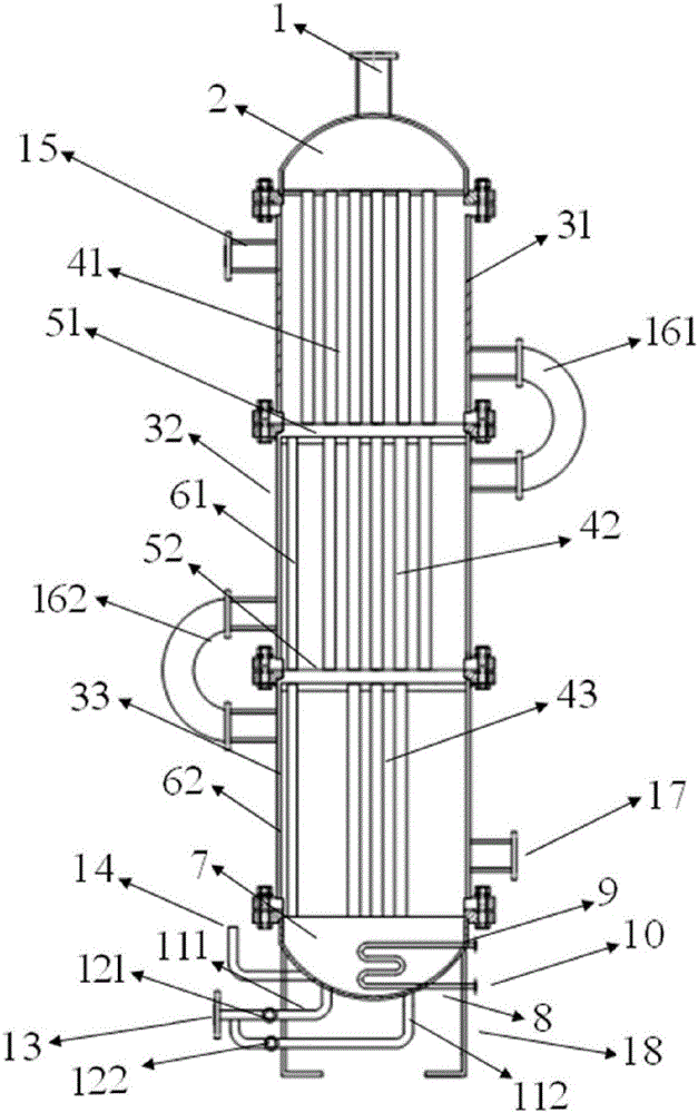
[0028] Such as figure 1 A cross-flow condensing heat exchanger shown includes a condenser body, an in-tube cooling unit and a subcooling unit. The condenser body includes a cylinder unit and a first seal head 2 and a second seal arranged on both sides of the cylinder body. Head 7, steam inlet 1 is provided on the first head 2, the cylinder unit includes a first cylinder 41, a second cylinder 42 and a third cylinder 43, the first cylinder 41 and the second cylinder 42, the first cylinder 41 The second cylinder 42 and the third cylinder 43 are respectively separated by the first vapor-liquid separator 51 and the second vapor-liquid separator 52, the cooling unit in the tube is arranged in the cylinder unit, and the supercooling unit is arranged in the second enclosure. Head 7; of which:

[0029] The in-tube cooling u...


PUM


Abstract

The invention provides a tubular condensation heat exchanger and a heat exchange method thereof. The condensation heat exchanger comprises a condenser body, a pipe-in cooling unit and a supercooling unit, wherein the condenser body comprises a tube body unit, a first seal head and a second seal head, the first seal head and the second seal head are arranged on both sides of the tube body, a steam inlet is formed in the first seal head, and the tube body unit comprises a first tube body, a second tube body and a third tube body; the first tube body is separated from the second tube body through a first gas-liquid separator, and the second tube body is separated from the third tube body through a second gas-liquid separator; the pipe-in cooling unit is arranged in the tube body unit, and the supercooling unit is arranged on the second seal head. The tubular condensation heat exchanger disclosed by the invention effectively uses a heat exchange area, quickly drains condensate, avoids the phenomena that the condensate is accumulated and two-phase flows are generated, and obviously increases the heat transfer coefficient.

Description

technical field [0001] The invention relates to thermal equipment in the technical field of efficient energy utilization, and in particular to a cross-flow condensation heat exchanger and a heat exchange method thereof. Background technique [0002] Condensing heat exchanger is a device that converts steam into liquid and takes away heat. It is widely used in chemical industry, refrigeration, petroleum, power and energy and other fields. After entering the condenser, the superheated steam undergoes three processes of cooling, saturated condensation and subcooling, releasing sensible heat and latent heat to achieve the purpose of heat exchange and steam condensation. In order to obtain a condensing heat exchanger with higher heat transfer performance, it should be avoided that the condensate covers the heat transfer surface to form a thick liquid film. [0003] At present, the mainstream enhanced condensation heat transfer technologies mainly include finned tubes, spiral gro...

Claims


Application Information

Patent Timeline
Patent Type & Authority Patents(China)
IPC IPC(8): F28D7/00F28B1/00
Inventor 贾力
Owner 福建蓝海节能科技有限公司
Why Eureka
Try Eureka