Control method and device for magnetic suspension bearing

A magnetic levitation bearing and control method technology, applied in the field of magnetic levitation, can solve the problem of insufficient displacement accuracy of the magnetic levitation system, and achieve the effect of improving the displacement accuracy

Active Publication Date: 2015-03-25
GREE ELECTRIC APPLIANCES INC +1
View PDF8 Cites 6 Cited by
  • Summary
  • Abstract
  • Description
  • Claims
  • Application Information

AI Technical Summary

Problems solved by technology

[0005] The main purpose of the present invention is to provide a control method for magnetic suspension bearings to solve the problem that the displacement accuracy in the magnetic suspension system is not high enough

Method used


Image

  • Control method and device for magnetic suspension bearing
  • Control method and device for magnetic suspension bearing
  • Control method and device for magnetic suspension bearing

Examples


Embodiment Construction

[0029] It should be noted that, in the case of no conflict, the embodiments in the present application and the features in the embodiments can be combined with each other. The present invention will be described in detail below with reference to the accompanying drawings and examples.

[0030] An embodiment of the present invention provides a control device for a magnetic suspension bearing, and the function of the device can be realized through an automatic control system.

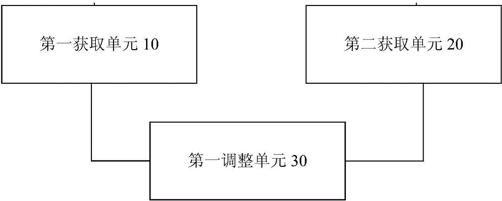
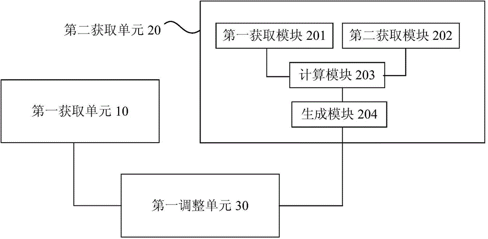
[0031] figure 2 is a schematic structural diagram of the control device for the magnetic suspension bearing according to the first embodiment of the present invention.

[0032] Such as figure 2 As shown, the control device for the magnetic suspension bearing includes a first acquisition unit 10 , a second acquisition unit 20 and a first adjustment unit 30 . The first acquisition unit 10 is used to acquire the speed feedback value of the center of the rotating shaft in the magnetic levitation system. ...


PUM


Abstract

The invention discloses a control method and a device for a magnetic suspension bearing. The control method for the magnetic suspension bearing comprises steps that, a speed feedback value of a rotation shaft center in a magnetic suspension bearing system is acquired; a speed reference value of the rotation shaft center is acquired; adjustment on the speed of the rotation shaft center is carried out according to the speed feedback value and the speed reference value. Through the method, displacement precision of the magnetic suspension system is improved.

Description

technical field [0001] The invention relates to the field of magnetic suspension, in particular to a control method and device for a magnetic suspension bearing. Background technique [0002] For a magnetic levitation system, the best control effect is that the displacement, velocity and acceleration of the center of the rotating shaft at the equilibrium position are all zero. [0003] The current magnetic levitation system adopts double closed-loop control, the outer loop is a displacement loop, and the inner loop is a current loop. The inventor found that, for the control method of the prior art, when the rotor reaches the balance position from the position deviated from the balance, the control current becomes 0, but the speed is not 0 at this time, therefore, the displacement in this way will be in the balance The position fluctuates back and forth all the time, and the displacement accuracy will be affected. The relationship between displacement, current Ic′ and veloc...

Claims


Application Information

Patent Timeline
Patent Type & Authority Applications(China)
IPC IPC(8): G01M1/38F16C32/04
Inventor 黄辉胡余生陈东锁李燕郭伟林胡叨福
Owner GREE ELECTRIC APPLIANCES INC
Why Eureka
Try Eureka