
Welding and shifting equipment for numerically-controlled machine tool

A CNC machine tool and equipment technology, applied in welding equipment, auxiliary welding equipment, welding/cutting auxiliary equipment, etc., can solve the problems of high labor intensity, low production efficiency, and high labor intensity for operators, and achieve the consistency of workpiece grouping Good, high precision of workpiece assembly, and the effect of improving production efficiency

Inactive Publication Date: 2015-12-02
WUHU RISHENG HEAVY DUTY MACHINE TOOLS
View PDF8 Cites 5 Cited by
  • Summary
  • Abstract
  • Description
  • Claims
  • Application Information

AI Technical Summary

Problems solved by technology

[0002] In the field of construction machinery, similar to the pair spot welding of parts such as excavation buckets, the pair spot welding tooling used is still in the state of too many sequences and manual compression of the workpieces, resulting in low accuracy of workpiece pairing, The occurrence of problems such as high labor intensity and low production efficiency for the operator
[0003] In the field of construction machinery, butt welding of parts similar to products such as excavation buckets is still in the state of too many sequences and manual sequence welding, which leads to problems such as high labor intensity for operators and low production efficiency.
This arc welding method is not only costly and labor-intensive, but also the welding quality can only be determined according to the worker's operating experience. Engaging in arc welding for a long time will also affect the health of the workers and even cause serious diseases.

Method used


Image

  • Welding and shifting equipment for numerically-controlled machine tool
  • Welding and shifting equipment for numerically-controlled machine tool
  • Welding and shifting equipment for numerically-controlled machine tool

Examples


Embodiment Construction

[0019] The preferred embodiments of the present invention will be described in detail below in conjunction with the accompanying drawings, so that the advantages and features of the present invention can be more easily understood by those skilled in the art, so as to define the protection scope of the present invention more clearly.

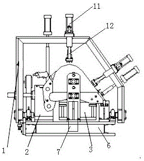
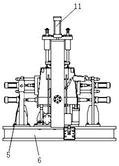
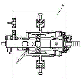
[0020] refer to Figure 1-5 , the specific implementation method adopts the following technical scheme: a kind of numerical control machine tool welding and its displacement equipment, including frame pressing mechanism 1, left and right positioning mechanism 2, side plate positioning mechanism 3, workbench 4, side plate pressing mechanism 5 , CNC machine tool 6 and controller 7, said CNC machine tool 4 is provided with a workbench 4, the periphery of the side plate positioning mechanism 3 is provided with a left and right positioning mechanism 2 and a side plate pressing mechanism 5, and the outside of the left and right positioning mechanism 2 i...


PUM


Abstract

The invention discloses welding and shifting equipment for a numerically-controlled machine tool, and relates to the field of engineering machines. The welding and shifting equipment comprises a rack pressing mechanism, a left-right locating mechanism, a side plate locating mechanism, a workbench, a side plate pressing mechanism, the numerically-controlled machine tool and a controller. The workbench is arranged on the numerically-controlled machine tool, the left-right locating mechanism and the side plate pressing mechanism are arranged on the periphery of the side plate locating mechanism, the rack pressing mechanism is arranged on the left-right locating mechanism, the left-right locating mechanism, the side plate locating mechanism and the side plate pressing mechanism are all arranged on the workbench, and the rack pressing mechanism comprises a pressing rod and an air cylinder connected with the pressing rod. The air cylinder and other automatic executing elements can be controlled by the controller, the welding and shifting equipment for the numerically-controlled machine tool is provided for the field of engineering machines, and is high in workpiece assembly precision and good in workpiece assembly consistency, the labor intensity of operators is fully lowered, and production efficiency is fully improved.

Description

technical field [0001] The invention relates to the field of engineering machinery, in particular to a numerically controlled machine tool welding and displacement equipment. Background technique [0002] In the field of construction machinery, similar to the assembly and spot welding of excavating buckets, the assembly and spot welding tooling used is still in the state of too many sequences and manual compression of the workpieces, resulting in low accuracy of workpiece assembly, Operator labor intensity is high, production efficiency is low and other problems occur. [0003] In the field of construction machinery, butt welding of parts such as excavating buckets is still in the state of too many sequences and manual sequence welding, which leads to problems such as high labor intensity for operators and low production efficiency. This arc welding method is not only costly and labor-intensive, but also the welding quality can only be determined according to the worker's...

Claims


Application Information

Patent Timeline
Patent Type & Authority Applications(China)
IPC IPC(8): B23K37/04B23K37/047
CPCB23K37/0435B23K37/047
Inventor 曹华兴樊宗保吴维祥刘海玲韩宁
Owner WUHU RISHENG HEAVY DUTY MACHINE TOOLS
Learn More