

Tank entering and exiting system and method
A trough system and a trough-in technology, which is applied in the direction of photographic technology, equipment, photographic auxiliary technology, etc., can solve the problems of high energy consumption, low equipment efficiency, and long empty time of the electrolytic cell, so as to achieve a high degree of environmental protection and save purchases Expenses for spare plates and short empty slot time
- Summary
- Abstract
- Description
- Claims
- Application Information
AI Technical Summary
Problems solved by technology
Method used
Image

Examples
Embodiment Construction
[0046] The specific implementation manner of the present invention will be described below in conjunction with the accompanying drawings.
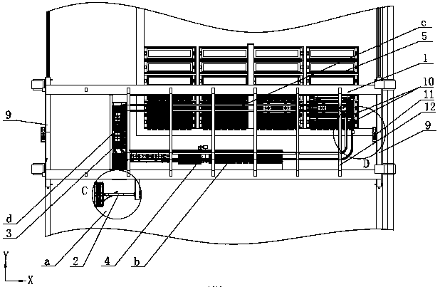
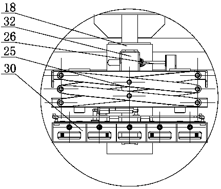
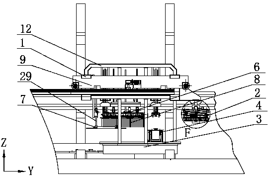
[0047] For the convenience of explanation, in figure 1 , figure 2 , image 3 The XYZ Cartesian coordinate system is marked in , the X-axis direction is the length direction of the main beam 1 of the cart, the Z-axis is the vertical axis, and the X-axis, Y-axis, and Z-axis directions are orthogonal to each other.
[0048] Such as figure 2 As mentioned above, the slot system of the present invention arranges four working areas in a ring, which are the feeding and discharging area a, the waiting area b, the working area c of the slot and the passivation area d along the counterclockwise direction. The middle annular track 10 is roughly in the shape of a rounded rectangle, wherein the area b to be entered and the working area c to enter and exit the tank are respectively located on the two long sides of the rectangle, most of the two long...
PUM
 Abstract
Description
Claims
Application Information