Tribometer

A tribology, friction contact technology, used in the field of rheometers, tribology units)

Active Publication Date: 2015-03-25
安东帕有限责任公司
View PDF11 Cites 10 Cited by
  • Summary
  • Abstract
  • Description
  • Claims
  • Application Information

AI Technical Summary

Problems solved by technology

[0019] However, the additional relatively soft spring 10, compared to the spring 20 in the system, poses a p

Method used


Image

  • Tribometer
  • Tribometer
  • Tribometer

Examples


Embodiment Construction

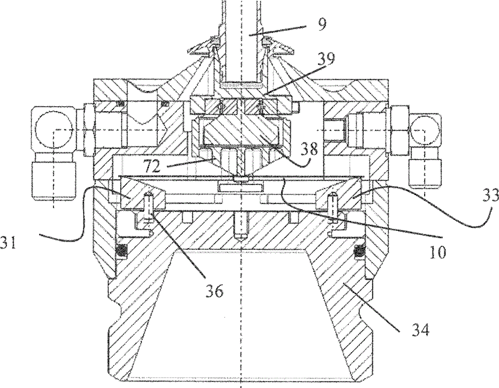
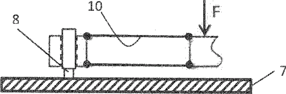
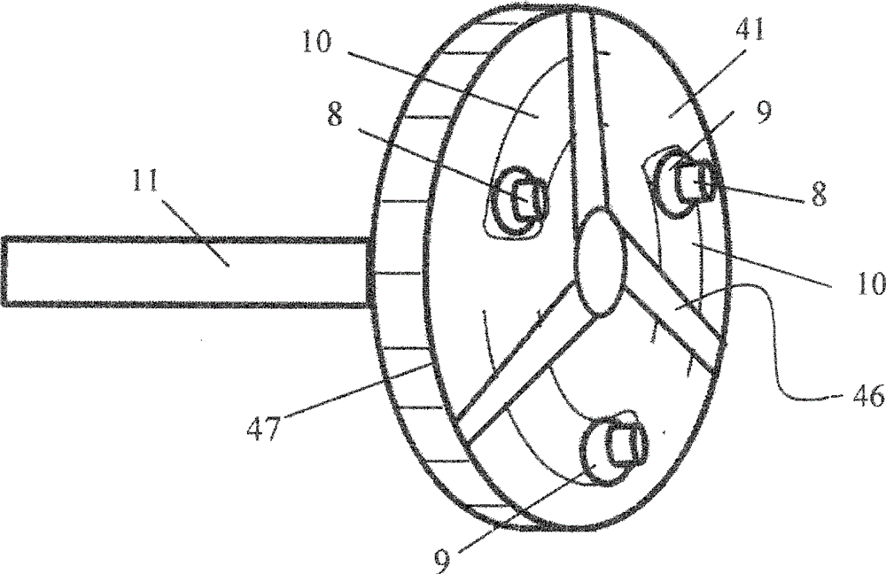
[0067] image 3 The shown rheometer 1 comprises a measuring motor 4 and a measuring shaft 6 connected to the measuring motor 4 , at the lower end of which a sample 7 in the form of a ball is mounted above it. By means of a normal force control unit, eg provided in the evaluation and control unit 40 , the sample 7 can be pressed against the underlying sample 8 with a defined force, in particular by the previous lowering of the suspension arm 5 a. Three lower samples 8 mounted symmetrically to each other in the form of blades are in frictional contact with the ball 7 . The blade 8 is supported by a holder 9 which is then supported by a spring 10 . The holder 9 and the spring 10 define a spring unit marked 3 which extends within the length of the arrow 3'. The spring constant of this spring unit 3 can advantageously (if necessary, automatically) be varied via the control and evaluation unit 40 by means of the adjustment mechanism or the adjustment unit 13 . The spring unit 3 i...


PUM


Abstract

The invention relates to a method and a device that determine tribological measured values of samples (7, 8) with a rheometer (1). Wherein the measuring parts of the rheometer (1) are replaced by samples (7, 8) and the surfaces of the samples (7, 8) are moved into frictional contact relative to each other. Accordingly, it is provided that all parts of the rheometer (1) holding the samples (7, 8) in frictional connection and frictional contact or forming the rheometer power circuit, including the spring unit (3) pressing the samples (7, 8) against each other, are regarded as an oscillatory circuit. The oscillation properties of the spring unit are regarded as relevant to the oscillation properties of the oscillatory circuit (30), and that the oscillation properties of the spring unit (3) are adjusted taking into consideration the resonance oscillations or effects produced by changing, different measurement conditions expected with the respective measurement.

Description

technical field [0001] The invention relates to the determination of tribological parameters and measured values ​​according to the preamble of patent claim 1 . Furthermore, the invention relates to a module (ie a tribological unit) for such a process according to the preamble of patent claim 8 . Finally, the invention concerns a rheometer according to the preamble of patent claim 13 for carrying out the method, if necessary using the modules according to the invention. Background technique [0002] By definition, rheology deals with the deformation and flow properties of substances. A rotational rheometer is a measuring device used to examine the rheological properties of samples of different materials. In this process, the measurement sample to be examined is introduced into a usually narrow measurement gap between two measurement parts which rotate and / or oscillate relative to each other and the material sample is subjected to shear between the measurement parts. Shear...

Claims


Application Information

Patent Timeline
IPC IPC(8): G01N11/00G01N19/02
CPCG01N11/142G01N19/02G01N11/14G01N33/30G01N11/00
Inventor F. 沃尔夫B. 鲍尔M. 克伦恩
Owner 安东帕有限责任公司
Why Eureka
Try Eureka