Fault diagnosis and positioning method for three-phase switch reluctance motor position sensor

A switch reluctance motor, sensor failure technology, applied in motor generator testing, instruments, measuring devices, etc., can solve the problem of position sensor failure, the switch reluctance motor is not suitable for acceleration and deceleration operation, motor commutation failure and other problems , to achieve the effect of extensive engineering application value, reliable diagnosis method, and avoid misdiagnosis

Inactive Publication Date: 2015-03-25
CHINA UNIV OF MINING & TECH
View PDF4 Cites 5 Cited by
  • Summary
  • Abstract
  • Description
  • Claims
  • Application Information

AI Technical Summary

Problems solved by technology

However, due to dust, collision and other reasons, the position sensor will fail, resulting in the loss of edge pulses after the failure
If the position sensor fails, the state of the position signal level will remain unchanged, resulting in motor commutation failure and affecting the smooth operation of the motor. Therefore, it is extremely important to diagnose the fault of the position sensor
Most of the traditional fault diagnosis methods based on interval time and fault diagnosis methods based on edge capture are suitable for the constant speed operation of switched reluctance motors, and are not suitable for the acceleration and deceleration operation of switched reluctance motors.

Method used


Image

  • Fault diagnosis and positioning method for three-phase switch reluctance motor position sensor
  • Fault diagnosis and positioning method for three-phase switch reluctance motor position sensor
  • Fault diagnosis and positioning method for three-phase switch reluctance motor position sensor

Examples


Embodiment Construction

[0031] An embodiment of the present invention will be further described below in conjunction with accompanying drawing:

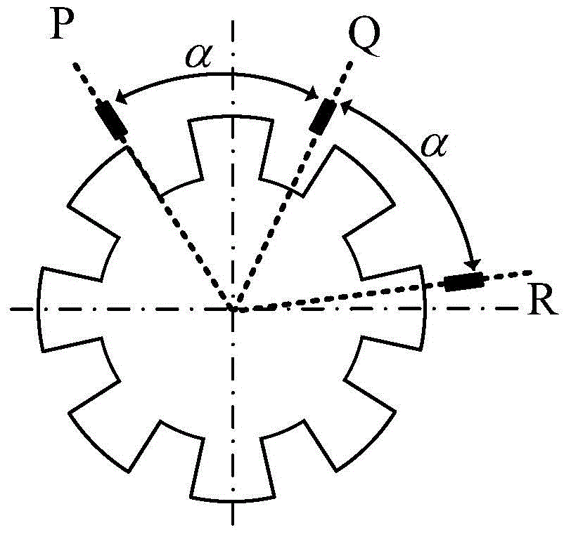
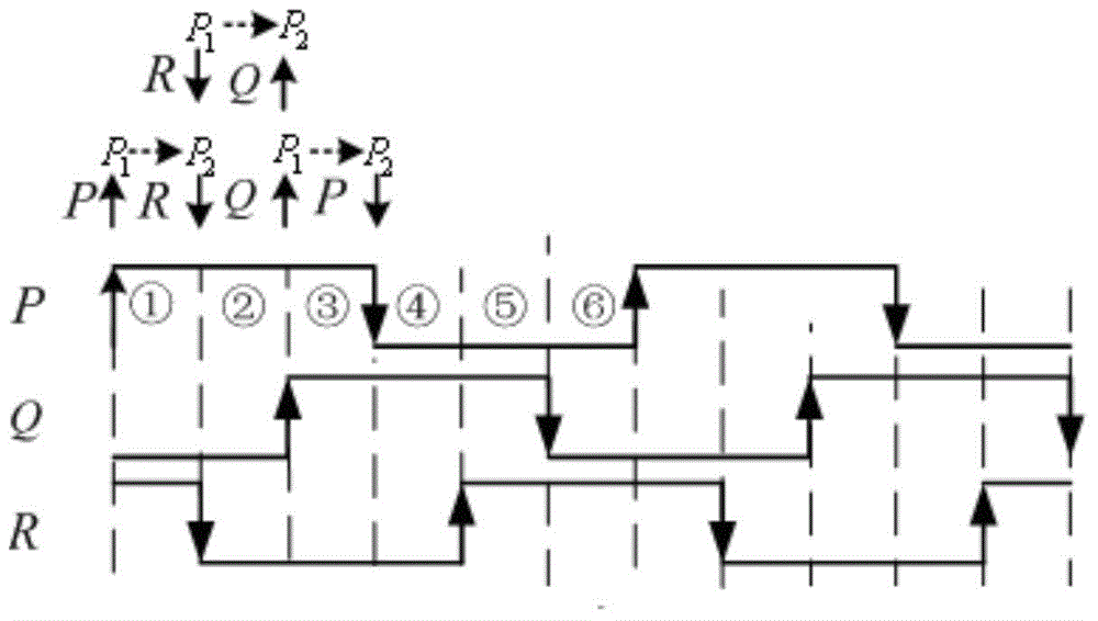
[0032] figure 1 Shown is a schematic diagram of the installation of three position sensors P, Q, R of a three-phase 12 / 8 structure switched reluctance motor. The three position sensors P, Q, R are installed at an angle α of 60 degrees, and the output signal of the position sensor is generated. like figure 2 As shown, the output signal phase of the position sensor P of the switched reluctance motor is earlier than the output signal phase of the position sensor Q in time, the output signal phase of the position sensor Q is earlier than the output signal phase of the position sensor R, and the output signal phase of the position sensor R The phase is earlier than the output signal phase of the position sensor P; the interval from the rising edge of the output signal of the position sensor P to the falling edge of the output signal of the position sensor R is...


PUM


Abstract

The invention discloses a fault diagnosis and positioning method for a three-phase switch reluctance motor position sensor. The method is suitable for performing fault diagnosis and positioning on three-phase times-of-three-phase various-topology structure rotary or linear switch reluctance motor position sensors. According to two edge pulse sequences adjacent to an output signal of the position sensor, whether a fault occurs on the position sensor or not is judged, and a fault diagnosis buffering region is set to avoid mistaken diagnosis; through distinguishing the output signal, of an edge pulse source, of the position sensor, the fault of the position sensor is positioned. The fault diagnosis and positioning method can be used for performing fault diagnosis and positioning on a single position sensor or multiple position sensors, speed changes of a motor do not affect diagnosis and positioning results, and the diagnosis method is reliable and high in practicability and has great engineering application value.

Description

technical field [0001] The invention relates to a method for fault diagnosis and positioning of a position sensor of a three-phase switched reluctance motor, especially suitable for fault diagnosis and positioning of a position sensor of a position sensor of a three-phase switched reluctance motor, multiple topological structures, and a rotary or linear switched reluctance motor. position. Background technique [0002] In the switched reluctance motor system, the position sensor signal can provide the basis for the speed calculation and motor commutation, which plays an extremely important role in the reliable operation of the system. However, due to dust, collision and other reasons, the position sensor will fail, resulting in the loss of the edge pulse after the failure. If the position sensor fails, the state of the position signal level will remain unchanged, resulting in failure of the motor commutation and affecting the smooth operation of the motor. Therefore, it is ...

Claims


Application Information

Patent Timeline
Patent Type & Authority Applications(China)
IPC IPC(8): G01R35/00G01R31/34
CPCG01R35/00
Inventor 陈昊韩国强程鹤王千龙王青王星
Owner CHINA UNIV OF MINING & TECH
Why Eureka
Try Eureka