
Display panel and display device

A technology for display panels and display devices, applied in nonlinear optics, instruments, optics, etc., can solve problems such as poor alignment, force difference, dark or bright line defects, eliminate adhesion differences, and reduce dark areas. Effect

Inactive Publication Date: 2015-03-25
SHENZHEN CHINA STAR OPTOELECTRONICS TECH CO LTD
View PDF6 Cites 8 Cited by
  • Summary
  • Abstract
  • Description
  • Claims
  • Application Information

AI Technical Summary

Problems solved by technology

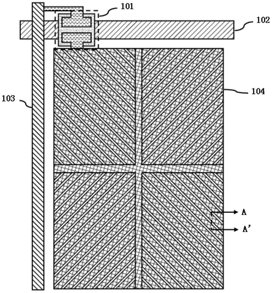
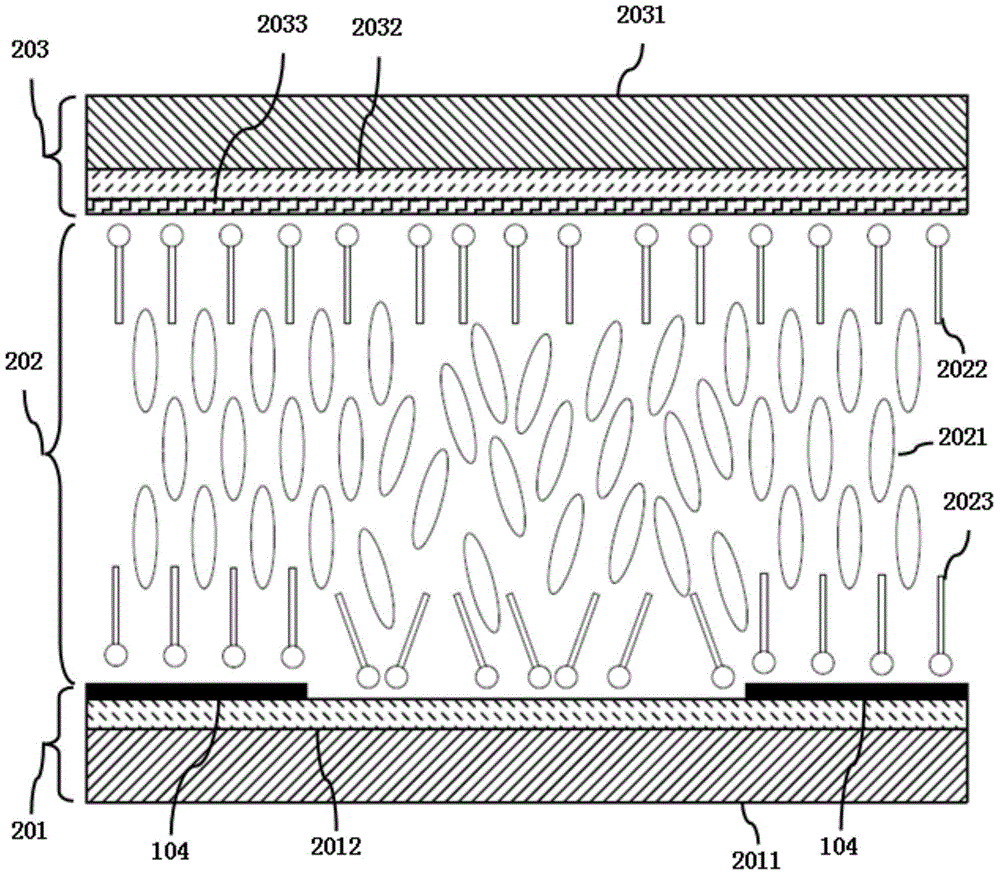
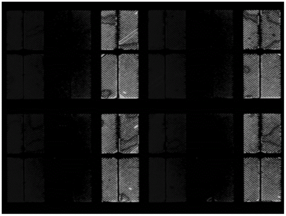
[0008] Since the pixel electrode area is partly covered by ITO 104, part is not covered by ITO 104, such as figure 1 and figure 2 As shown, when the auxiliary alignment agent (2022, 2023) is adsorbed on the substrate surface for alignment without using the PI alignment layer, due to the difference between ITO 104 and SiNx2012 on the substrate surface, the auxiliary alignment agent (2022, 2023) The difference in force between the surface of the substrate and the substrate causes poor alignment, and it is easy to cause dark or bright line defects after the voltage is applied. The display effect is as follows: image 3 shown

Method used


Image

  • Display panel and display device
  • Display panel and display device
  • Display panel and display device

Examples


Embodiment Construction

[0032] The word "embodiment" as used in this specification means serving as an example, instance or illustration. Furthermore, the article "a" as used in this specification and the appended claims may generally be construed to mean "one or more" unless specified otherwise or clear from the context in the singular.

[0033] refer to Figure 4 with Figure 5 , Figure 4 is a partial schematic view of the display panel of the present invention, Figure 5 for Figure 4 Schematic diagram of the first embodiment of the middle BB' section.

[0034] The display device in this embodiment includes a backlight module and a display panel, and the display panel and the backlight module are aligned and combined into one body. Wherein, the display panel includes a color filter substrate 503 , a thin film transistor array substrate 501 and a liquid crystal layer 502 . The color filter substrate 503 and the thin film transistor array substrate 501 are aligned and combined into one body, ...


PUM


Abstract

The invention discloses a display panel and a display device. The display panel comprises a color filter substrate, a liquid crystal layer and a thin film transistor array substrate. The color filter substrate is provided with a first protection layer and a common electrode layer, the thin film transistor array substrate is provided with a second protection layer and a pixel electrode, and the common electrode layer and the pixel electrode are oppositely arranged; the liquid crystal layer comprises liquid crystal molecules, first auxiliary orientation agent molecules and second auxiliary orientation agent molecules, the color filter substrate and the thin film transistor array substrate are aligned and combined into a whole, and the liquid crystal layer is arranged between the color filter substrate and the thin film transistor array substrate. The display panel and the display device can eliminate differences of adhesive force of the second auxiliary orientation agent molecules on different portions of a pixel region, and therefore the occurrence frequency of dark spaces is reduced.

Description

【Technical field】 [0001] The present invention relates to the field of display technology, in particular to a display panel and a display device. 【Background technique】 [0002] In the conventional technology, in order to arrange the liquid crystal molecules in a VA (Vertical Alignment, vertical alignment) LCD (Liquid Crystal Display, liquid crystal display) vertically to the surface of the substrate, the liquid crystal molecules are generally subjected to vertical alignment treatment. [0003] The most common practice at present is to apply an alignment agent on specific areas of the upper and lower substrate surfaces. The alignment agent generally contains a large amount of chemical solvents, such as NMP (N-methylpyrrolidone) and polymer materials polyimide (Polyimide, PI) and other components, and then bake the substrate at high temperature (generally above 200 degrees Celsius) for a long time to dry the solvent in the alignment agent, thereby forming a PI alignment layer...

Claims


Application Information

Patent Timeline
Patent Type & Authority Applications(China)
IPC IPC(8): G02F1/139G02F1/1337G02F1/1343G02F1/1335
CPCG02F1/1337G02F1/133703G02F1/133707G02F1/134309G02F1/1368
Inventor 钟新辉李泳锐
Owner SHENZHEN CHINA STAR OPTOELECTRONICS TECH CO LTD
Learn More