Cached data disk brushing method and device

A technology of caching data and flashing disks, applied in the storage field, can solve the problems of low efficiency of flashing disks of controllers

Active Publication Date: 2015-03-25
HUAWEI CLOUD COMPUTING TECH CO LTD
View PDF7 Cites 31 Cited by
  • Summary
  • Abstract
  • Description
  • Claims
  • Application Information

AI Technical Summary

Problems solved by technology

[0005] The present invention provides a method and device for flashing cached data to solve the problem of low efficiency of flashing controllers in the prior art

Method used


Image

  • Cached data disk brushing method and device
  • Cached data disk brushing method and device
  • Cached data disk brushing method and device

Examples


Embodiment 2

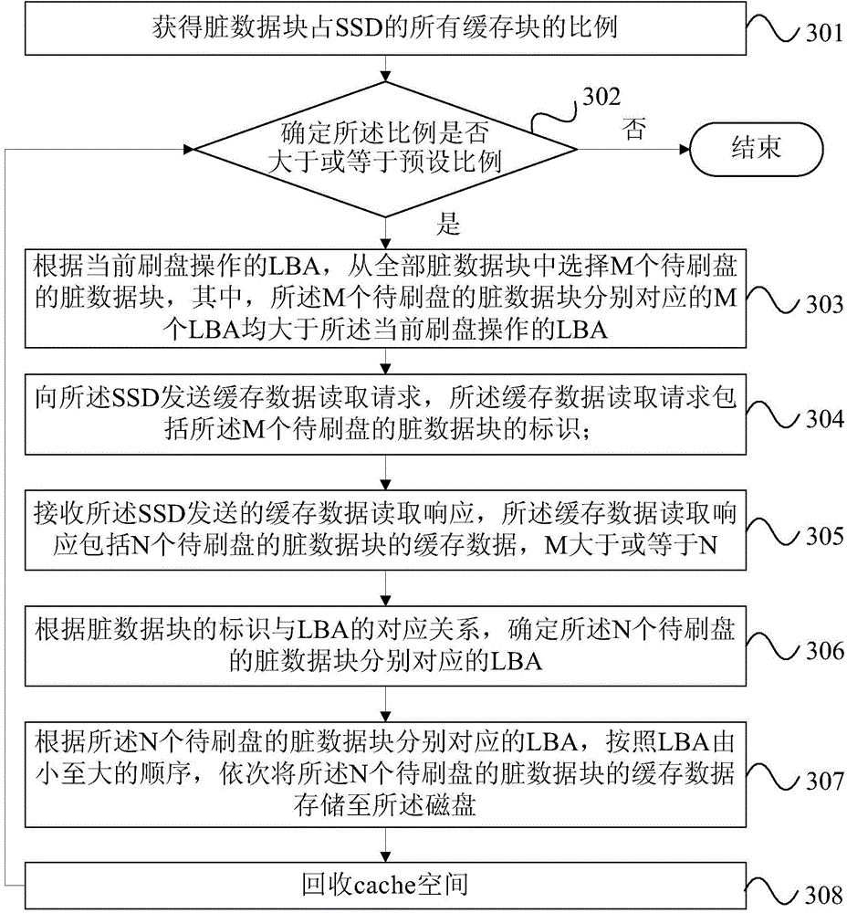
[0094] Optionally, on the basis of Embodiment 1 of the controller of the present invention, the read request sending module 601 is further configured to: select the M data blocks to be brushed from all dirty data blocks according to the LBA of the current disk brushing operation. Dirty data blocks, wherein the M LBAs respectively corresponding to the M dirty data blocks to be flashed are larger than the LBAs of the current flashing operation.

[0095] Optionally, the read request sending module 601 is specifically configured to: put each dirty data block into the first queue or the second queue according to the LBA of the current disk brushing operation and the LBA of each dirty data block , the LBA of the dirty data blocks in the first queue is greater than the LBA of the current disk brushing operation, and the LBA of the dirty data blocks in the second queue is smaller than the LBA of the current disk brushing operation; from the first Select the M dirty data blocks to be f...

Embodiment 3

[0099] Optionally, on the basis of the second embodiment of the controller of the present invention, the read request sending module 601 is further configured to: according to the selected LBAs of the M dirty data blocks to be flashed, send the M pending The dirty data blocks of the LBA in the dirty data blocks of the flash disk are merged to obtain the combined dirty data blocks to be brushed; correspondingly, the read request sending module 602 is specifically used for: sending cached data reads to the SSD A fetch request, the cache data read request includes the identifier of the merged dirty data block to be flushed.

[0100] The controller of this embodiment can be used to execute Figure 4 The implementation principles and technical effects of the technical solutions of the shown method embodiments are similar and will not be repeated here.

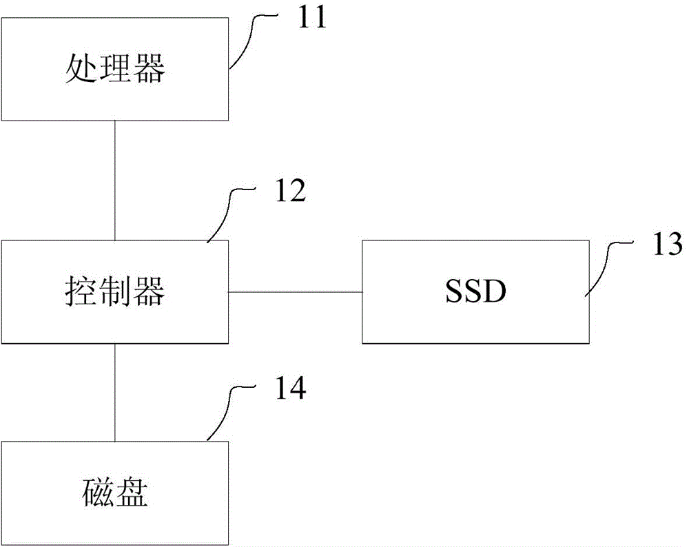
[0101] Figure 7 It is a structural schematic diagram of the fourth embodiment of the controller of the present invention, as ...

Embodiment 5

[0104] Optionally, on the basis of the fourth embodiment of the controller of the present invention, the processor 703 is further configured to: select the M dirty data blocks to be flashed from all dirty data blocks according to the LBA of the current flashing operation, Wherein, the M LBAs respectively corresponding to the M dirty data blocks to be flashed are larger than the LBAs of the current flashing operation.

[0105] Optionally, the processor 703 is specifically configured to: put each dirty data block into the first queue or the second queue according to the LBA of the current disk brushing operation and the LBA of each dirty data block, the The LBA of the dirty data block in the first queue is greater than the LBA of the current brushing operation, and the LBA of the dirty data block in the second queue is smaller than the LBA of the current brushing operation; select from the first queue Dirty data blocks of the M disks to be flushed.

[0106] Further optionally, ...


PUM


Abstract

The invention provides a cached data disk brushing method and device. The cached data disk brushing method is applied to a storage system. The storage system comprises a controller, a disk and an SSD, wherein the SSD serves as a cache of the disk. The cached data disk brushing method is executed by the controller and comprises the steps of sending a cached data reading request to the SSD, wherein the cached data reading request includes identifications of dirty data blocks of M disks to be brushed; receiving cached data reading request response sent by the SSD, wherein the cached data reading request response includes cached data of dirty data blocks of N disks to be brushed, and the M is greater than or equal to the N; determining LBA respectively corresponding to the dirty data blocks of the N disks according to the corresponding relation of the identifications of the dirty data blocks and the LBA; sequentially storing the cached data of the dirty data blocks of the N disks in the disk according to the LBA respectively corresponding to the dirty data blocks of the N disks and in an LBA sequence from small to large.

Description

technical field [0001] Embodiments of the present invention relate to storage technologies, and in particular to a method and device for flashing cached data. Background technique [0002] With the maturity of Solid State Drive (SSD) technology and the decrease of cost, more and more storage systems begin to use SSD as a cache medium. [0003] In the prior art, when the storage system performs write caching through the cache technology: the controller first receives the write request issued by the processor, wherein the write request includes the data to be written and the logical block address corresponding to the data to be written ( LBA, Logical Block Address); secondly, write the data to be written into the cache block of the SSD, set the status of the cache block as a dirty data block, and the identity of the dirty data block corresponds to the data to be written LBA performs associative storage; finally, at the timing of flashing the cache, data synchronization is car...

Claims


Application Information

Patent Timeline
Patent Type & Authority Applications(China)
IPC IPC(8): G06F12/08G06F3/06
CPCG06F12/08
Inventor 张志乐
Owner HUAWEI CLOUD COMPUTING TECH CO LTD
Why Eureka
Try Eureka