Vertical type adjustable take-up reel

A take-up reel, vertical technology, applied in the field of vertical adjustable take-up reel, can solve the problems of copper wire being stretched or even broken, unable to wind the cable, messy, etc., to avoid being pulled Stretch or even be broken, better take-up effect, easy to manufacture

Active Publication Date: 2015-03-25
WUHU CHANGRUN SPECIAL COPPER
View PDF6 Cites 10 Cited by
  • Summary
  • Abstract
  • Description
  • Claims
  • Application Information

AI Technical Summary

Problems solved by technology

[0002] In the cable manufacturing industry, the take-up reel plays an important role. It can make messy cables wound together in an orderly manner, and it is convenient Unwinding; however, the previous take-up reel was short and short, and it was impossible to wind a large number of cables at one time. If a large amount of winding (horizontal direction) is performed, the cables will break away from the shackles and become messy, especially It is a copper wire that has high requirements for the weight of a single produc

Method used


Image

  • Vertical type adjustable take-up reel

Examples


Embodiment 1

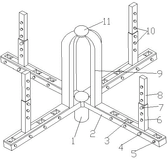
[0018] Such as figure 1 As shown, a vertical adjustable take-up reel includes a rotating shaft 1 and a take-up chassis 2. There are 3-6 take-up chassis 2 which are horizontally fixed on the top of the rotating shaft 1 at equal intervals. The wire chassis 2 includes a limit roller and a take-up roller 9. The limit roller includes a roller sleeve 6 and a roller rod 8. The roller sleeve 6 is sheathed with the roller rod 8, the roller sleeve 6 and the roller rod 8. The same side is horizontally provided with several second threaded holes 10 at equal intervals, and the second screw 7 passes through the second threaded holes 10 on the same side of the roller sleeve 6 and the roller rod 8 and then is fixed by a nut; A take-up roller 9 is vertically fixed on the upper end surface of the wire take-up chassis 2 on the side close to the rotating shaft 1, and the upper end surface of the wire take-up chassis 2 facing away from the shaft 1 is provided with several grooves 3 at equal interva...

Embodiment 2

[0022] Same as Embodiment 1, the difference is that there are three wire take-up chassis 2, which can realize the completion of the basic wire take-up operation, save steel materials, and reduce costs.

Embodiment 3

[0024] The same as Embodiment 1, the difference is that there are 5 wire take-up chassis 2, which can ensure a more stable wire take-up process.


PUM


Abstract

The invention discloses a vertical type adjustable take-up reel and belongs to the field of machining equipment. The vertical type adjustable take-up reel comprises a rotating shaft and three to six take-up base plates, each take-up base plate comprises limiting rollers and a take-up roller, the take-up base plates are fixed to the top end of the rotating shaft, each limiting roller comprises a roller sleeve and a roller rod, each roller rod is sleeved with the corresponding roller sleeve, second threaded holes are formed in the same side faces of each roller rod and the corresponding roller sleeve, and each roller rod and the corresponding roller sleeve are fixed through a second screw; the upper end face of each take-up base plate is fixedly provided with the corresponding take-up roller and grooves, the roller sleeves are arranged in the grooves, first threaded holes are formed in the side faces of each take-up base plate and penetrate through the corresponding grooves, threaded holes are also formed in the positions, corresponding to the first threaded holes, of the roller sleeves when the roller sleeves are disposed in the grooves, and the roller sleeves are fixed in the grooves through first screws. The limiting rollers are arranged on the upper end faces of the take-up base plates, so that adjustability of the distance between the take-up rollers and the limiting rollers and the overall height of the limiting rollers is achieved; thus, taking up of cable coils of different sizes and heights can be achieved, and the limiting rollers can also prevent the phenomenon that cables get rid of restraint in the transverse direction and are in a mess when plenty of winding is conducted.

Description

technical field [0001] The invention belongs to the field of mechanical processing equipment, and more specifically relates to a vertical adjustable take-up reel. Background technique [0002] In the cable manufacturing industry, the take-up reel occupies an important position. It can make the messy cables be wound together in an orderly manner, and it is convenient to unwind; It is impossible to wind a large number of cables at one time. If a large amount of winding (horizontal direction) is carried out, the cables will be unbound and messy, especially for the weight of the product and the elongation and tensile properties of the product. Copper wires with higher requirements, especially copper wires with large weight per room, high product elongation and low tensile performance, are prone to be stretched or even broken during the winding process. appear; and at present, none of the existing take-up reels can take up wire reels of different sizes, and different take-up re...

Claims


Application Information

Patent Timeline
IPC IPC(8): H01B13/00B65H54/40
Inventor 程叙毅
Owner WUHU CHANGRUN SPECIAL COPPER
Why Eureka
Try Eureka