
Mechanical interlocking transmission device of isolating switches

A technology of isolating switch and transmission device, which is applied in the direction of air switch components, etc., can solve the problems of deformation of interlocking components and transmission parts, failure to meet the needs of use, failure to meet mechanical interlocking, etc., to achieve reliable transmission, satisfying limited positioning, The effect of flexible and convenient movement

Active Publication Date: 2015-03-25
CHINA XD ELECTRIC CO LTD
View PDF7 Cites 2 Cited by
  • Summary
  • Abstract
  • Description
  • Claims
  • Application Information

AI Technical Summary

Problems solved by technology

Especially in the isolating switch products needed in the 550kV-1100kV AC power transmission project, the existing technology cannot meet the requirements of reliable mechanical interlocking and electrical interlocking between the isolating switch and the earthing switch of the earthing switch, and due to the transmission distance Even if interlocking is installed in the prior art, the interlocking elements and transmission parts will be deformed and damaged during interlocking, which cannot meet the needs of use

Method used


Image

  • Mechanical interlocking transmission device of isolating switches
  • Mechanical interlocking transmission device of isolating switches
  • Mechanical interlocking transmission device of isolating switches

Examples


Embodiment Construction

[0030] The present invention will be further described in detail below in conjunction with specific embodiments, which are explanations of the present invention rather than limitations.

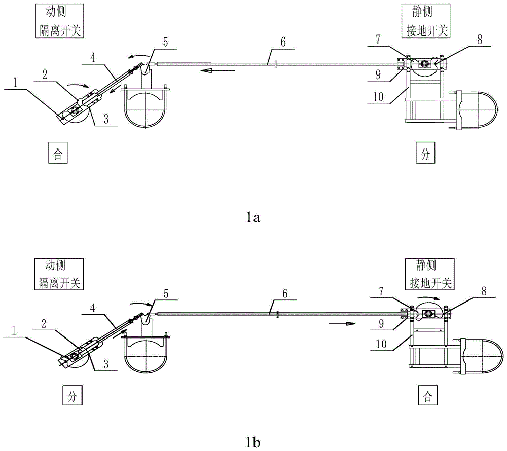
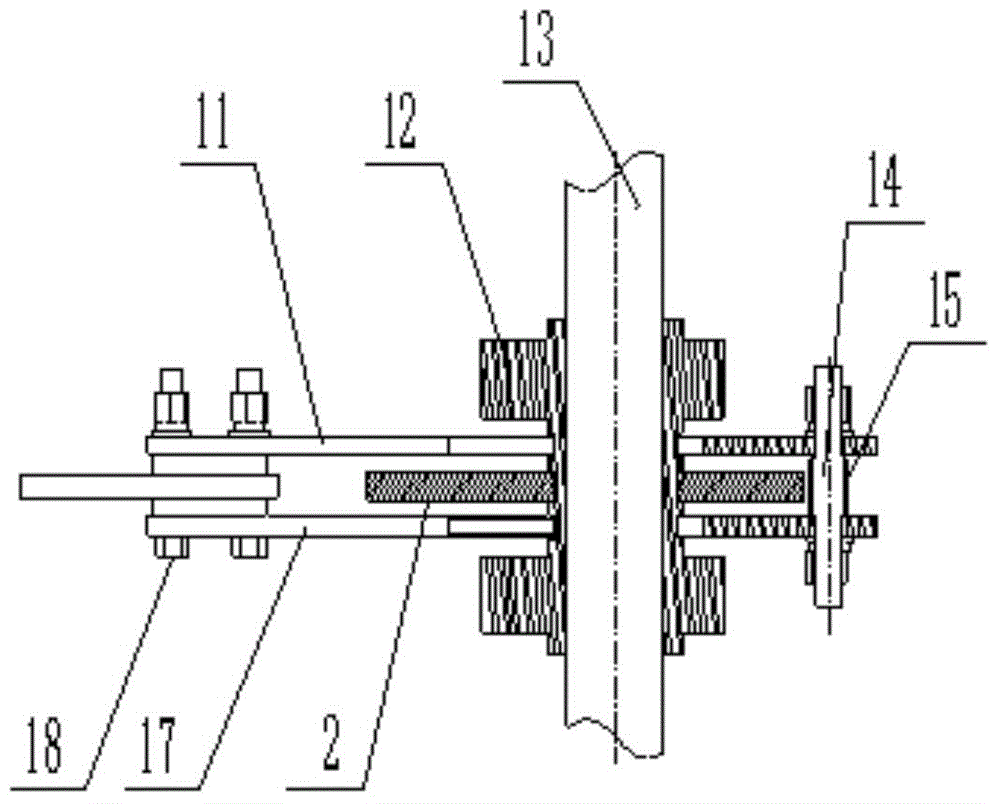
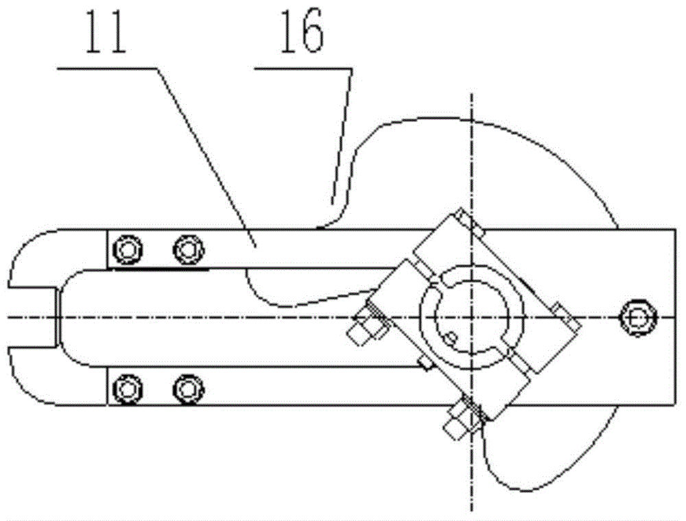
[0031] The present invention is a kind of isolating switch mechanical interlock transmission device, such as figure 1 As shown, it includes a transmission device 5, a mechanical locking device on the moving side and a mechanical locking device on the static side; the mechanical locking device on the moving side is connected to the vertical connecting rod 13 on the moving side of the isolating switch, and is used to control the closing and opening of the isolating switch on the moving side. The static-side mechanical locking device is connected to the static-side vertical connecting rod 28 of the isolating switch for closing and opening control of the static-side isolating switch; the moving-side mechanical locking device and the static-side mechanical locking device are respectively fixed with...


PUM


Abstract

The invention discloses a mechanical interlocking transmission device of isolating switches. The transmission device comprises a transmission device body, a moving-side mechanical locking device and a fixed-side mechanical locking device. The moving-side mechanical locking device is connected to a moving-side vertical connecting rod of the isolating switches and used for controlling closing and opening of the isolating switch on the moving side. The fixed-side mechanical locking device is connected to a fixed-side vertical connecting rod of the isolating switches and used for controlling closing and opening of the isolating switch on the fixed side. A moving-side pulling rod and a fixed-side pulling rod are fixedly arranged on the moving-side mechanical locking device and the fixed-side mechanical locking device respectively, and the free end of the moving-side pulling rod is connected with the free end of the fixed-side pulling rod through the transmission device body for transmission. When the isolating switch on the moving side is closed, the earthing switch on the fixed side is opened; when the isolating switch on the moving side is opened, the earthing switch on the fixed side is closed. Control over the switch on the moving side and the switch on the fixed side is achieved through the correspondingly arranged moving-side mechanical locking device and fixed-side mechanical locking device, interlocking of the moving side and the fixed side is completed through transition of the transmission device body, and therefore single-side switch closing is achieved in the same state.

Description

technical field [0001] The invention relates to the field of high-voltage isolating switch design, in particular to a mechanical interlocking transmission device of an isolating switch. Background technique [0002] For a long time, the 550kV-1100kV isolating switch products produced at home and abroad have been far away from the power source of the isolating switch due to the long distance between the grounding switch and the static contact side, so it is impossible to achieve precise transmission, and the mechanical power loss is relatively large. The safe operation of the grounding switch on the static contact side is realized by the design institute as an independent grounding unit through the interlocking of secondary control appliances. [0003] In recent years, with the continuous growth of my country's power system capacity and the continuous expansion of high-voltage power grids, users have higher and higher performance requirements for power equipment. Especially ...

Claims


Application Information

Patent Timeline
IPC IPC(8): H01H31/08
CPCH01H31/08
Inventor 王宇驰司小伟莫冰周昊明邢宏昌蒋伟
Owner CHINA XD ELECTRIC CO LTD
Learn More