Array substrate, manufacturing method of array substrate and display device
A technology of an array substrate and a manufacturing method, which is applied in the display field, can solve problems such as the reduction of luminance of OLED display panels, and achieve the effects of improving display effects and reducing unevenness
- Summary
- Abstract
- Description
- Claims
- Application Information
AI Technical Summary
Problems solved by technology
Method used
Image

Examples
Embodiment 1
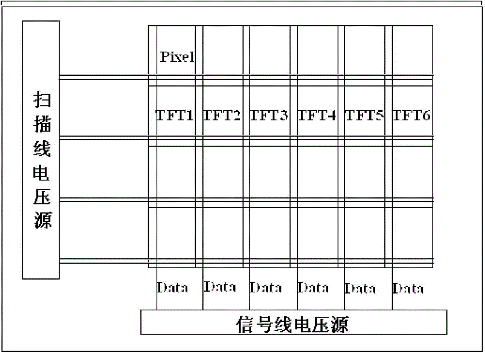
[0037] This embodiment provides an array substrate, including a plurality of scanning lines and a plurality of data lines formed on the substrate, the plurality of scanning lines and the plurality of data lines are interlaced to define a plurality of pixel units and A thin film transistor is formed in the pixel unit, wherein, in the direction from close to the scan line voltage source to away from the scan line voltage source, the channel width-to-length ratio of the N+M thin film transistor is greater than the channel width of the Nth thin film transistor Length ratio, N and M are both integers greater than 1.
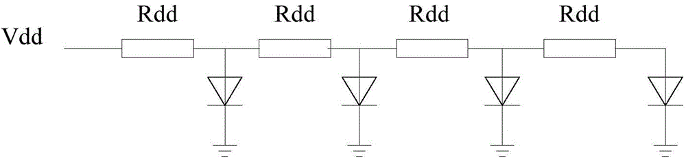
[0038] The magnitude of the charging current of the thin film transistor is proportional to the channel width-to-length ratio W / L of the thin-film transistor charging channel, W represents the channel width, and L represents the channel length. Therefore, the channel width-to-length ratio of the thin film transistor can be increased To increase the charging current of...
Embodiment 2
[0045] An embodiment of the present invention further provides a display device, including the above-mentioned array substrate. The structure and working principle of the array substrate are the same as those of the above-mentioned embodiment, and are not repeated here. In addition, the structures of other parts of the display device may refer to the prior art, which will not be described in detail herein. The display device can be: liquid crystal panel, OLED panel, electronic paper, liquid crystal TV, liquid crystal display, digital photo frame, mobile phone, tablet computer and other products or components with any display function.
Embodiment 3
[0047] This embodiment also provides a method for fabricating an array substrate, including forming a plurality of scan lines and a plurality of data lines on the substrate, and the plurality of scan lines and the plurality of data lines are interlaced to define a plurality of pixel units , and a thin film transistor is formed in the pixel unit, wherein, from the direction close to the scan line voltage source to the direction away from the scan line voltage source, a channel width to length ratio greater than that of the Nth thin film transistor is formed. N+M thin film transistors.
[0048] The size of the charging current of the thin film transistor is proportional to the channel width to length ratio W / L of the charging channel of the thin film transistor, W represents the channel width, and L represents the channel length. Therefore, the channel width to length ratio of the thin film transistor can be increased by increasing to increase the charging current of the thin fi...
PUM
 Abstract
Description
Claims
Application Information
 - Generate Ideas
- Intellectual Property
- Life Sciences
- Materials
- Tech Scout
- Unparalleled Data Quality
- Higher Quality Content
- 60% Fewer Hallucinations
Browse by: Latest US Patents, China's latest patents, Technical Efficacy Thesaurus, Application Domain, Technology Topic, Popular Technical Reports.
© 2025 PatSnap. All rights reserved.Legal|Privacy policy|Modern Slavery Act Transparency Statement|Sitemap|About US| Contact US: help@patsnap.com