Input voltage overvoltage protection circuit

An overvoltage protection circuit and input voltage technology, which is applied to emergency protection circuit devices, overvoltage-responsive protection, circuit devices, etc., can solve the problem of heat generation, difficulty in ensuring circuit safety, stress on electrolytic capacitors, and main power switch tubes. Insufficient and other problems, to achieve the effect of overvoltage protection

Active Publication Date: 2015-03-25
INVENTRONICS HANGZHOU
View PDF6 Cites 12 Cited by
  • Summary
  • Abstract
  • Description
  • Claims
  • Application Information

AI Technical Summary

Problems solved by technology

[0002] When the power supply works in a high-voltage input environment, the electrolytic capacitors and main power switch tubes in the power supply are prone to insufficient stress, which will cause serious heating. If the circuit does not have an overvoltage protection function, it is easy to cause a fire. The conventional overvoltage protection circuit consists of It is composed of overvoltage detection module, protection control module and relay. The overvoltage detection module is used to detect the input voltage. When the input voltage reaches the overvoltage detection reference value, the protection control module sends a signal to turn off the relay, but it needs to be reset after disconnecting the relay. At this time, the input AC voltage may be just at the peak value. At this time, a high surge current will be generated in the input circuit, and the circuit safety is difficult to be guaranteed.

Method used


Image

  • Input voltage overvoltage protection circuit
  • Input voltage overvoltage protection circuit
  • Input voltage overvoltage protection circuit

Examples


Embodiment Construction

[0034] The following will clearly and completely describe the technical solutions in the embodiments of the present invention with reference to the accompanying drawings in the embodiments of the present invention. Obviously, the described embodiments are only some, not all, embodiments of the present invention. Based on the embodiments of the present invention, all other embodiments obtained by persons of ordinary skill in the art without making creative efforts belong to the protection scope of the present invention.

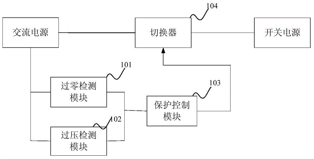
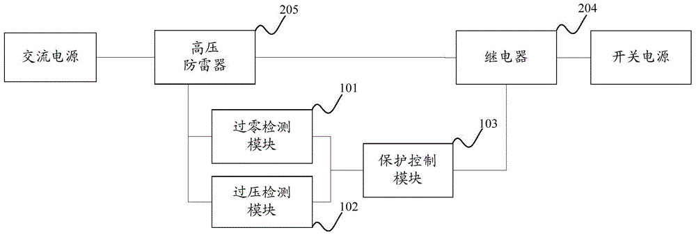
[0035] The purpose of the present invention is to provide an input voltage overvoltage protection circuit, the protection circuit is arranged between the AC power supply and the switching power supply, including: a zero-crossing detection module 101, an overvoltage detection module 102, a protection control module 103 and a switch 104;

[0036] The zero-crossing detection module 101 is connected to the AC power supply, and is used to compare the instantaneous ...


PUM


Abstract

The invention discloses an input voltage overvoltage protection circuit which comprises a zero crossing detection module, an overvoltage detection module, a protection control module and a switcher. The zero crossing detection module is used for detecting whether the input voltage provided by an alternating current power source is in a zero crossing time frame or not. The overvoltage detection module is used for detecting whether overvoltage occurs in the input voltage provided by the alternating current power source or not. The protection control module is used for controlling the switcher to be disconnected when overvoltage occurs in the input voltage and controlling the switcher to return to the breakover state when overvoltage does not occur in the input voltage and the input voltage is in the zero crossing time frame. According to the protection circuit, when overvoltage occurs in the input voltage, the switcher is controlled to be disconnected, and the switcher is controlled to be in the breakover state again when overvoltage does not occur in the input voltage and the input voltage is in the zero crossing time frame; due to the fact that when the switcher is in the breakover state again, and the input voltage is in the zero crossing time frame, the situation that when the switcher resets again, the circuit is damaged due to excessively high input voltage is avoided, and the overvoltage protection of the input voltage can be achieved safely and effectively accordingly.

Description

technical field [0001] The invention and the field of overvoltage protection, in particular, relate to an input voltage overvoltage protection circuit. Background technique [0002] When the power supply works in a high-voltage input environment, the electrolytic capacitors and main power switch tubes in the power supply are prone to insufficient stress, which will cause serious heating. If the circuit does not have an overvoltage protection function, it is easy to cause a fire. The conventional overvoltage protection circuit consists of It is composed of overvoltage detection module, protection control module and relay. The overvoltage detection module is used to detect the input voltage. When the input voltage reaches the overvoltage detection reference value, the protection control module sends a signal to turn off the relay, but it needs to be reset after disconnecting the relay. At this time, the input AC voltage may be just at the peak value. At this time, a high surge...

Claims


Application Information

Patent Timeline
Patent Type & Authority Applications(China)
IPC IPC(8): H02H3/20H02H3/06
Inventor 钟永裕任明明徐迎春
Owner INVENTRONICS HANGZHOU
Why Eureka
Try Eureka