Two-stage low-pass filtering and amplifying, peak clipping and pulse modulation system based on linear driving

A pulse wave modulation and low-pass filtering technology, applied in the field of electronics, can solve the problem of low power and achieve the effect of preventing use and service life

Inactive Publication Date: 2015-03-25
CHENGDU SIMAO TECH
View PDF0 Cites 4 Cited by
  • Summary
  • Abstract
  • Description
  • Claims
  • Application Information

AI Technical Summary

Problems solved by technology

[0003] The purpose of the present invention is to overcome the defect that the output power of the traditional pulse wave circuit is not high and cannot meet people's increasing electrical needs, and to provide a two-stage low-pass filter amplification and peak clipping pulse modulation system based on linear drive

Method used


Image

  • Two-stage low-pass filtering and amplifying, peak clipping and pulse modulation system based on linear driving
  • Two-stage low-pass filtering and amplifying, peak clipping and pulse modulation system based on linear driving

Examples


Embodiment

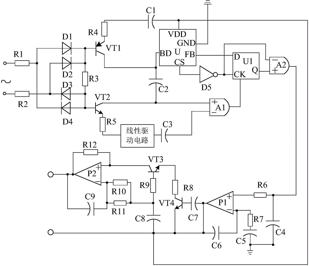
[0016] Such as figure 1 As shown, the linear drive-based two-stage low-pass filtering and amplifying peak-clipping pulse wave modulation system of the present invention mainly includes a peak-clipping circuit, a pulse-wave modulation circuit connected to the output terminal of the peak-clipping circuit, and a pulse-wave modulation circuit The two-stage low-pass filter amplifier circuit connected to the output end; also includes a linear drive circuit arranged between the peak clipping circuit and the pulse wave modulation circuit.

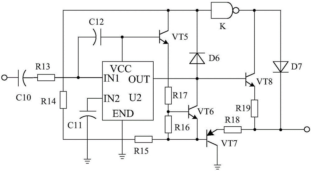
[0017] Such as figure 2 As shown, the linear drive circuit is composed of the drive chip U2, the transistor VT5, the transistor VT6, the transistor VT7, and the transistor VT8. The positive pole is connected to the peak shaving circuit, and the negative pole is connected to the IN1 pin of the drive chip U2 through the resistor R13. Polar capacitor C10, one end is connected to the collector of the transistor VT5, the other end is connected to the base...


PUM


Abstract

The invention discloses a two-stage low-pass filtering and amplifying, peak clipping and pulse modulation system based on linear driving. The system mainly comprises a peak clipping circuit, a pulse modulation circuit and a two-stage low-pass filtering and amplifying circuit, wherein the pulse modulation circuit is connected with the output end of the peak clipping circuit, and the two-stage low-pass filtering and amplifying circuit is connected with the output end of the pulse modulation circuit. The system is characterized by further comprising a linear driving circuit arranged between the peak clipping circuit and the pulse modulation circuit; the linear driving circuit is composed of a driving chip U2, a triode VT5, a triode VT6, a triode VT7, a triode VT8, a polar capacitor C10, a resistor R14 and the like; the positive electrode of the polar capacitor C10 is connected with the peak clipping circuit, and the negative electrode of the polar capacitor C10 is connected with a pin IN1 of the driving chip U2 after passing through a resistor R13; one end of the resistor R14 is connected with the collector electrode of the triode VT5, and the other end of the resistor R14 is connected with the base electrode of the triode VT7 after passing through a resistor R15. Under the action of the linear driving circuit, the system can provide a stable voltage and prevent the situation that the using effect and the service life of an electric appliance are affected by an unstable voltage.

Description

Technical field [0001] The invention relates to the field of electronics, in particular to a linear drive-based two-stage low-pass filter amplifying peak-clipping pulse wave modulation system. Background technique [0002] The application of electrical energy is becoming more and more popular in social production and human life, and electrical appliances that meet various requirements continue to appear. In life, people usually use pulse wave modulation circuits to power electrical appliances to meet people's use of electrical appliances. However, in actual use, the output power of the pulse wave modulation circuit is not high, which cannot meet people's increasing demand for electrical appliances. Summary of the invention [0003] The purpose of the present invention is to overcome the shortcomings that the output power of the traditional pulse circuit is not high and cannot meet the increasing demand for electric appliances, and to provide a two-stage low-pass filter amplifying ...

Claims


Application Information

Patent Timeline
Patent Type & Authority Applications(China)
IPC IPC(8): H02M3/156H02M1/32
CPCH02M1/32H02M3/156
Inventor 何梅谢彬
Owner CHENGDU SIMAO TECH
Why Eureka
Try Eureka