Radio frequency equipment calibration method

A technology of radio frequency equipment and calibration method, which is applied in transmitter monitoring, receiver monitoring, etc., and can solve problems such as complex process, low efficiency, and high error rate

Active Publication Date: 2015-03-25
SHENZHEN GONGJIN ELECTRONICS CO LTD
View PDF8 Cites 11 Cited by
  • Summary
  • Abstract
  • Description
  • Claims
  • Application Information

AI Technical Summary

Problems solved by technology

[0003] Radio frequency equipment has strict requirements on radio frequency performance. However, at present, radio frequency equipment is still in the stage of manual calibration, with complex process, low efficiency and high error rate.

Method used


Image

  • Radio frequency equipment calibration method
  • Radio frequency equipment calibration method

Examples


Embodiment Construction

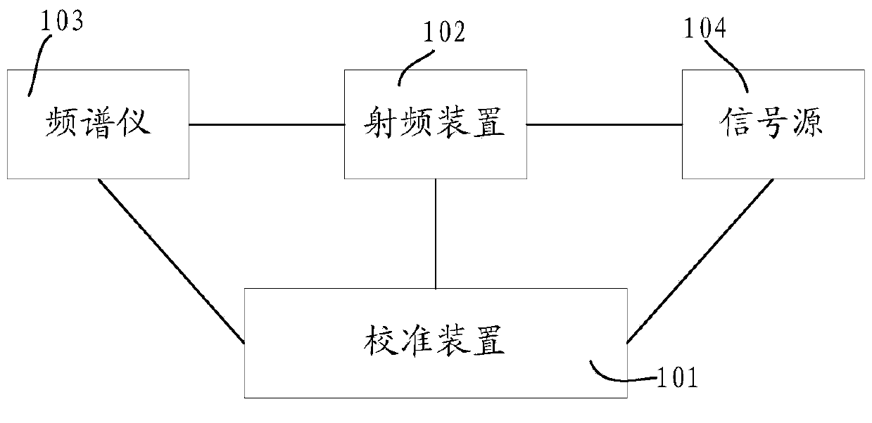
[0024] Such as figure 1 As shown, it is a hardware architecture diagram for implementing a radio frequency device calibration method in a preferred embodiment of the present invention, including: a calibration device 101 , a radio frequency device 102 , a spectrum analyzer 103 and a signal source 104 .

[0025] The calibration device 101 is connected to the radio frequency device 102, the spectrum analyzer 103 and the signal source 104 through a network cable, and uses the point-to-point protocol (ie PPP) in the wireless local area network telnet to realize the calibration device 101 and the radio frequency device 102, the spectrum analyzer The communication between 103 and the signal source 104 satisfies the real-time monitoring of the performance parameters of the radio frequency device 102 by the calibration device 101 .

[0026] The radio frequency device 102 is connected to the spectrum analyzer 103 and the signal source 104 respectively.

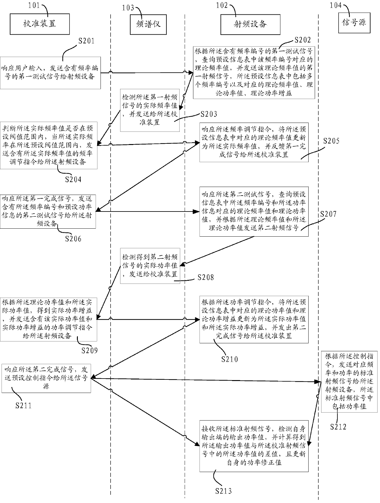
[0027] Such as figure 2 As s...


PUM


Abstract

The invention discloses a radio frequency equipment calibration method. The calibration method is applied to a calibration device, radio frequency equipment, a frequency spectrograph and a signal source; the calibration device is connected with the radio frequency equipment, the frequency spectrograph and the signal source through a cable, the radio frequency equipment is respectively connected with the frequency spectrograph and the signal source. The automatic calibration of each of frequency, power and power gain of the radio frequency equipment is realized through a calibration instruction preset by the calibration device and a feedback instruction preset by the radio frequency equipment, and the calibration efficiency and precision are improved.

Description

technical field [0001] The invention relates to an electronic equipment debugging technology, in particular to a radio frequency equipment calibration method. Background technique [0002] Radio frequency equipment is an electronic device used to receive or transmit radio frequency signals. For example, in the field of mobile communication, base stations are divided into macro base stations, microcellular base stations, Femtocell home base stations and other radio frequency equipment according to the coverage of the signal. The signal coverage radius of the macro base station can reach 5 kilometers, which can meet the wide outdoor communication; the signal coverage of the Femtocell home base station is about 50 meters, mainly for indoor communication, which solves the problem that the signal of the macro base station passes through buildings. Meet the problem of normal communication. Femtocell home base stations are connected to mobile communication operator networks throug...

Claims


Application Information

Patent Timeline
Patent Type & Authority Applications(China)
IPC IPC(8): H04B17/11H04B17/21
Inventor 刘立刚杨汉锋罗凤云葛锋
Owner SHENZHEN GONGJIN ELECTRONICS CO LTD
Why Eureka
Try Eureka