Axial flow exhaust turbine

An exhaust turbine and axial flow technology, which is applied in the direction of machines/engines, engine functions, stators, etc., can solve the problems of performance degradation, cost increase, and overall size of the turbine, and achieve damage prevention, easy maintenance, and Cost suppression effect of maintenance expenditure

Active Publication Date: 2015-03-25
MITSUBISHI POWER LTD
View PDF10 Cites 2 Cited by
  • Summary
  • Abstract
  • Description
  • Claims
  • Application Information

AI Technical Summary

Problems solved by technology

[0002] Problems in the low-pressure section airfoil of steam turbines are: performance degradation (wet loss) caused by drainage (water droplets) generated in wet steam, acid corrosion caused by drainage impact of the drainage hitting the turbine part
Therefore, maintenance work due to acid corrosion damage increases and costs increase
[0012] In addition, if pipes are used to connect the drain flow path of the vane and the exhaust chamber as in Patent Document 2, the pipes protrude to the outside of the vehicle cabin, and the overall size of the turbine becomes larger.
Therefore, a large room in which a large turbine installation space can be secured is required, which causes an increase in cost

Method used


Image

  • Axial flow exhaust turbine
  • Axial flow exhaust turbine
  • Axial flow exhaust turbine

Examples


no. 1 approach 〕

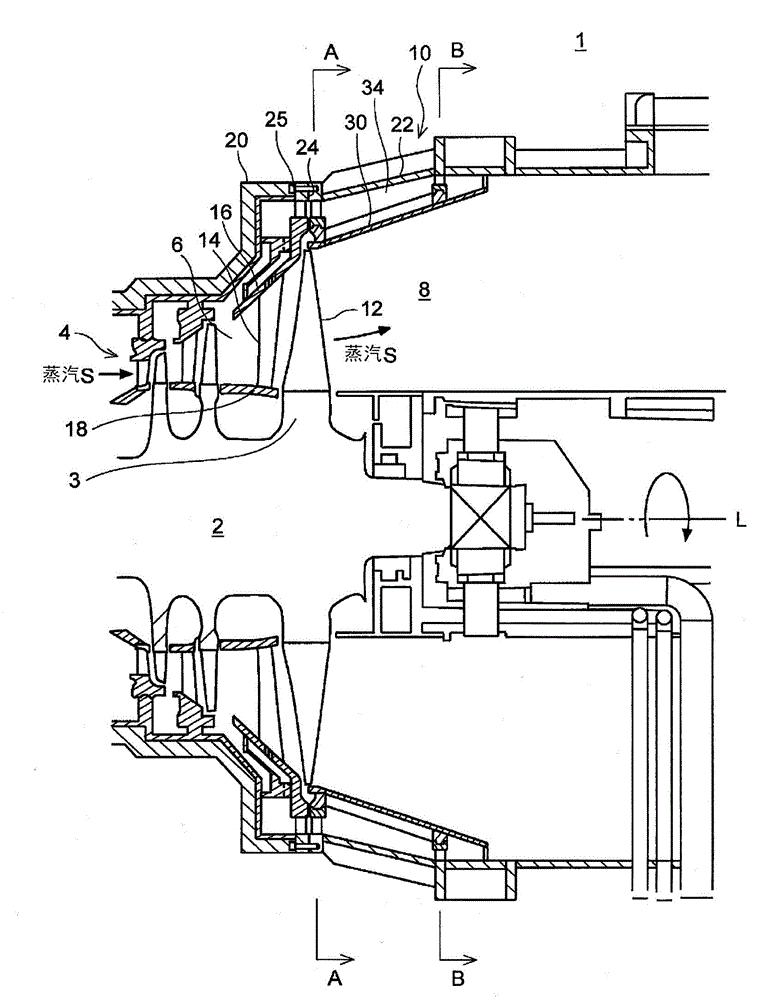
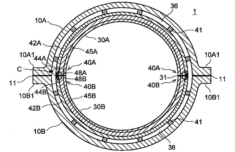
[0062] figure 1 is a cross-sectional view showing the overall configuration of the axial flow exhaust turbine according to the first embodiment, figure 2 yes figure 1 The A-A line sectional view of the axial flow exhaust turbine shown, image 3 yes figure 1 The B-B line sectional view of the axial flow exhaust turbine shown, Figure 4 It is a sectional view of main parts showing the periphery of the inner partition wall of the axial flow exhaust turbine. It should be noted, Figure 4 shown with figure 1 Figures of the same section (vertical section).

[0063] Such as figure 1 As shown, the axial flow exhaust turbine 1 has: a rotor 2, an airfoil 4 arranged around the rotor 2, a steam passage 6 passing through the airfoil 4, an exhaust chamber 8 provided on the downstream side of the steam passage 6, and an internal A vehicle interior 10 with a steam passage 6 and an exhaust chamber 8 .

[0064] The rotor 2 is supported rotatably with respect to the cabin 10 . A plura...

no. 2 approach 〕

[0093] Next, an axial flow exhaust turbine provided with an inner partition wall different from that of the first embodiment will be described as a second embodiment. The structure of this embodiment is the same as that of the first embodiment except that the structure of the inner partition wall is different.

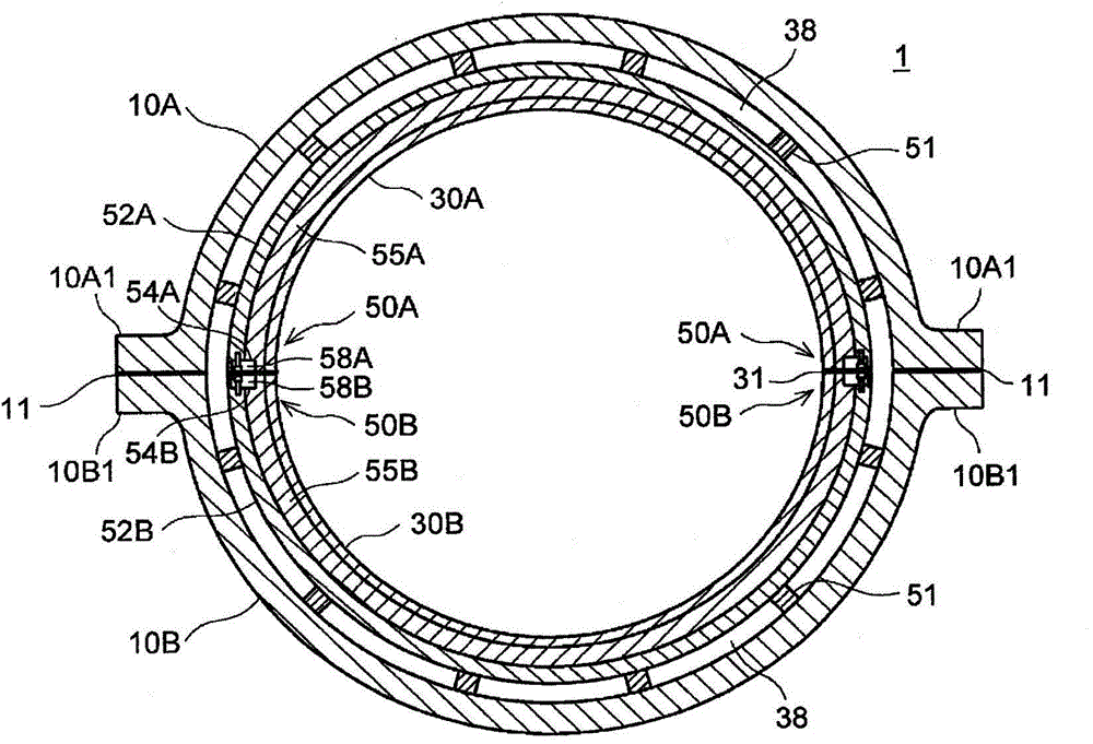
[0094] Figure 8 is a sectional view showing the overall structure of the axial flow exhaust turbine according to the second embodiment, Figure 9 It is a sectional view of main parts showing the periphery of the inner partition wall of the axial flow exhaust turbine according to the present embodiment. Figure 10 yes means Figure 9 An enlarged view of part E of the positioning structure of the inner partition wall on the upstream side shown, Figure 11 yes Figure 10 Front view of line F-F shown.

[0095] It should be noted that the same names and symbols are used for the same structures, components, and the like as those of the first embodiment, and detailed de...


PUM


Abstract

[Problem] To provide an axial flow exhaust turbine which enables smooth discharge from a steam path to a drain, reduces the cost of part replacement, and saves space. [Solution] The axial flow exhaust turbine (1) includes: a steam passage (6) in which steam passage rotator blades (12) and stator blades (14) have been arranged; an exhaust chamber (8) provided downstream from the steam passage (6) for discharging steam from the steam passage (6) in the axial direction of the turbine; a drive chamber (10) including the steam passage (6) and the steam chamber (8); and an interior barrier (30) provided on the inner periphery of the drive chamber (10) facing the steam chamber (8). A drain passage (34) is formed between the drive chamber (10) and the interior barrier (30) through which drainage recovered from the steam passage (6) is able to pass.

Description

technical field [0001] The present invention relates to an axial flow exhaust turbine in which the steam passing through the airfoils is discharged along the axial direction of the turbine, in particular to an axial flow exhaust turbine equipped with a mechanism for discharging the drain water from the steam passages in which the airfoils are arranged. flat. Background technique [0002] Problems in the low-pressure section airfoils of steam turbines are performance degradation (moisture loss) caused by drainage (water droplets) generated in wet steam, and acid corrosion caused by drainage impact of the drainage hitting turbine parts. Therefore, a steam turbine equipped with a mechanism for discharging drain water in wet steam from a steam passage of the turbine is considered. For example, Patent Document 1 discloses a structure in which slits are provided along the circumferential direction on an outer ring holding a stator blade, whereby drainage in steam is discharged ou...

Claims


Application Information

Patent Timeline
Patent Type & Authority Applications(China)
IPC IPC(8): F01D25/32F01D9/02
CPCF01D25/30F01D25/32F05D2220/31F01D25/24F01D25/243F01D25/246F05D2260/602F05D2260/608
Inventor 长尾秀人白井广和尾崎太一巽康之
Owner MITSUBISHI POWER LTD
Why Eureka
Try Eureka