
Unit For Connecting Parts

A technology for connecting parts and components, applied in the direction of connecting components, furniture connectors, key connections, etc., can solve the problems of weak joints, impossible and difficult wide planks, etc.

Inactive Publication Date: 2015-03-25
维达里基库祖耶维斯 +1
View PDF8 Cites 18 Cited by
  • Summary
  • Abstract
  • Description
  • Claims
  • Application Information

AI Technical Summary

Problems solved by technology

[0003] The disadvantage of this technical solution is that such connectors can only be used to connect narrow planks with rails; however, the connection of wide planks is almost impossible, since it is extremely difficult to prevent locking of the planks during alignment; moreover , the joint is weak during bending because of the stress concentration at the bending point
[0011] The disadvantage of this prototype is that it only allows the joining of flat parts, but there is an urgent need to join parts bounded by curved surfaces such as spherical or elliptical surfaces

Method used


Image

  • Unit For Connecting Parts
  • Unit For Connecting Parts
  • Unit For Connecting Parts

Examples


Embodiment Construction

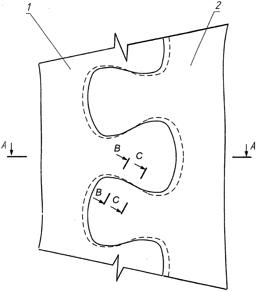
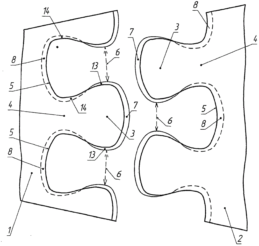
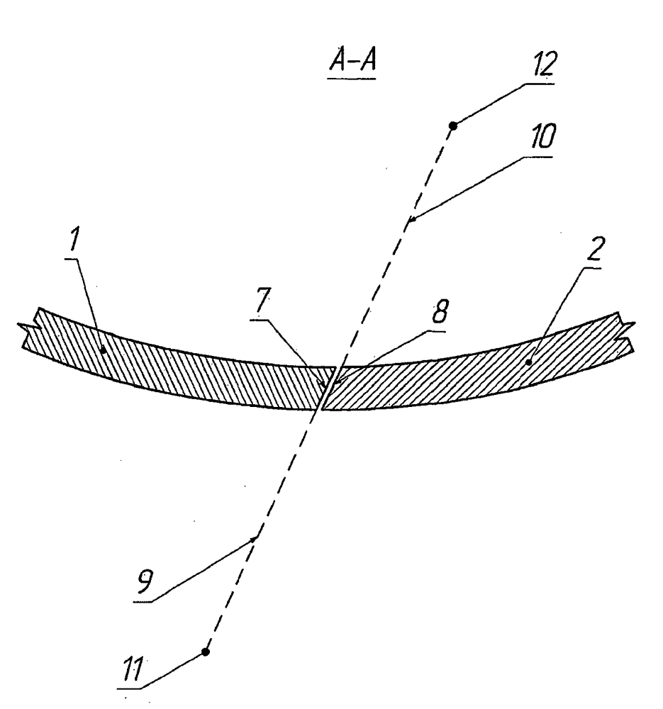
[0027] A joint for joining parts 1 and 2 having a curved surface, in this particular example a spherical surface, comprising protrusions and complementary grooves, said protrusions being arranged on the mating sides of the parts, said The protrusion has a spherical widening 3 at its end and a neck 4 at its base, said complementary recess in the form of a spherical cavity 5 corresponding to the spherical widening 3 of the protrusion and becoming into a narrow channel 6 that cooperates with the raised neck 4 . The surface 7 of the raised end and the surface 8 of the bottom of the groove cooperating therewith have a conical shape. The guide path 9 of the conical surface 7 passes through the apex 11 and the guide path 10 of the conical surface 8 passes through the apex 12, the apexes 11 and 12 being arranged on opposite sides with respect to the parts to be connected.

[0028] By moving the straight segment 15 along the guide path 16 (see Figure 7 ) form the side surface 13 of ...


PUM


Abstract

The invention relates to detachable connections of parts, primarily rigid parts, and can be used, in particular, for connecting elements of building structures. The unit for connecting parts with a curvilinear surface comprises protrusions which are formed on those sides of the parts which are to be joined, said protrusions having bulb-like enlargements at the ends and necks at the bases thereof, and grooves which are complementary to the protrusions and constitute bulb-like recesses corresponding to the bulb-like enlargements of the protrusions and merging into cavities corresponding to the necks of the protrusions.; The surfaces of the ends of the protrusions and adjoining surfaces of the bottom of the grooves have a conical shape, and the vertices of the surfaces of the ends of the protrusions and of the bottom of the grooves are arranged along different sides relative to the parts to be connected, the lateral surfaces of the protrusions and adjoining lateral surfaces of the grooves are formed by moving a straight line along a guide, which constitutes an intersecting line of a spherical surface with a cylindrical surface formed by moving the straight line along an S-like guide. The lateral surfaces of the protrusions and the lateral surfaces of the grooves are smoothly joined to the surfaces of the ends of the protrusions and surfaces of the bottom of the grooves, respectively.

Description

technical field [0001] The invention relates to a detachable connection for parts, mainly rigid parts, and in particular for connecting elements of architectural structures such as transparent domes, equipment frames, furniture and toy elements. Background technique [0002] A known tongue-and-groove type connection is known from RU 2063158 C1. This structure is used to connect the end surfaces of wooden planks that cooperate with each other by longitudinal sides with transverse rails, wherein the means for connecting the planks with rails to each other consist of cooperating grooves and protrusions with dovetail shoulders. formed together. The shoulders are inclined relative to a plane perpendicular to the plank reference plane, and the inclination is towards the raised and grooved edges. [0003] The disadvantage of this technical solution is that such connectors can only be used to connect narrow planks with rails; however, the connection of wide planks is almost imposs...

Claims


Application Information

Patent Timeline
Patent Type & Authority Applications(China)
IPC IPC(8): F16B5/07A63H33/08
CPCA63H33/08F16B5/07F16B3/00A63H33/082F16B5/008A47B2230/0077F16B3/04F16B5/126F16B17/008
Inventor 维达里基·库祖耶维斯叶夫根尼·尤利维奇·格列科夫
Owner 维达里基库祖耶维斯
Learn More