Special die for stamping inward bending part and stamping method

A technology of internal bending and mold, which is applied in the field of stamping molds, can solve problems such as the inability to guarantee the size of product parts, and achieve the effects of improving mold life, high fillet strength, and ensuring the accuracy of forming dimensions

Active Publication Date: 2015-04-01
山东省未来人才科技有限公司
View PDF6 Cites 8 Cited by
  • Summary
  • Abstract
  • Description
  • Claims
  • Application Information

AI Technical Summary

Problems solved by technology

Due to the above defects, the size of the product parts cannot be guaranteed by using the

Method used


Image

  • Special die for stamping inward bending part and stamping method
  • Special die for stamping inward bending part and stamping method
  • Special die for stamping inward bending part and stamping method

Examples


Example Embodiment

[0033] Attached below Figure 1-14 An embodiment of the present invention is described.

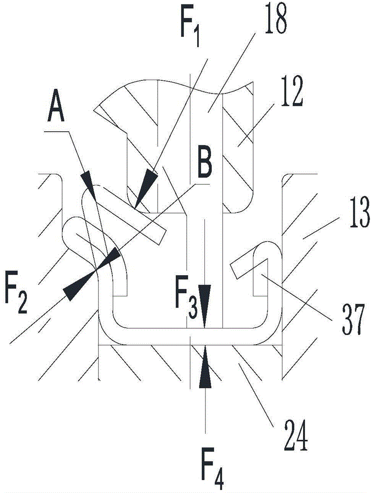
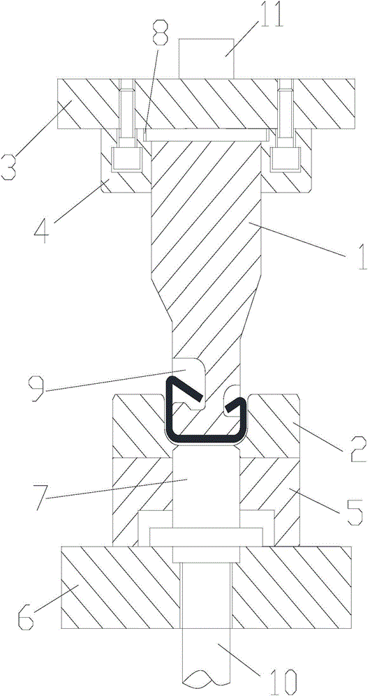
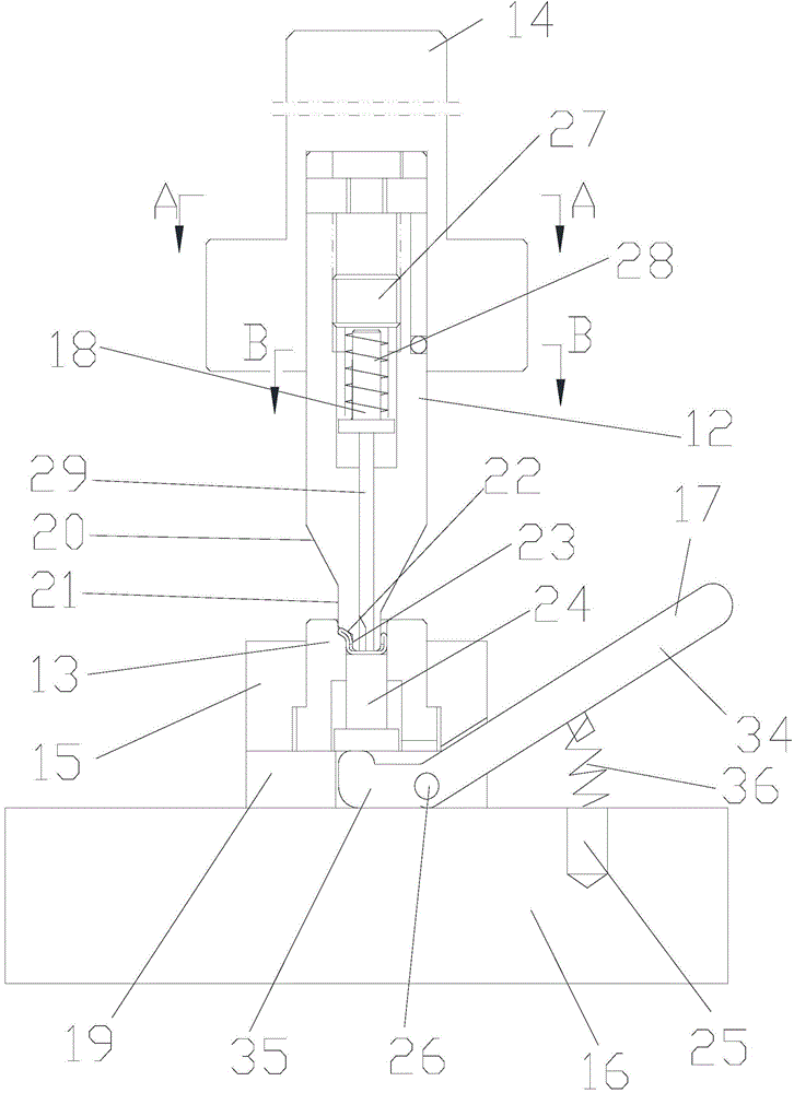
[0034] A special mold for stamping internally bent parts. It has a first mold assembly and a second mold assembly. The first mold assembly includes a male mold I1, a female mold I2, a mold upper plate 3, a fixed plate 4, a cushion frame 5, and a mold. Lower plate 6 and ejector 7, said punch I1 with relief grooves 9 on both sides of the lower end; said second mold assembly includes punch II12, female mold II13, mold handle II14, mold base 15, and lower mold plate 16. And the crowbar 17, the lower part of the punch II 12 is made with a V-shaped transition section 20, the lower part of the V-shaped transition section 20 is made with a straight section 21, and one side of the straight section 21 is made with an inclined stamping section below 22. The lower part of the inclined stamping forming section 22 is formed with a direct pressure forming section 23, and the bottom of the direct pressing ...


PUM


Abstract

The invention discloses a special die for stamping an inward bending part and a stamping method. The special die for stamping the inward bending part is provided with a first die component and a second die component, a bottom round angle of a blank is precisely bent through the first die component, and the second die component bends the blank into the part shape which conforms to size requirements based on keeping the bottom round angle. The special die for stamping the inward bending part has high practical value.

Description

Technical field [0001] The invention belongs to the technical field of stamping dies, and in particular relates to a special die and a stamping method for stamping inner bending parts. Background technique [0002] Existing teaching materials, professional design tool materials, atlas cases, most of them introduce the classic U-shaped, V-shaped, Shape, huff Stamping and bending forming process and related die design. And the shape is inwardly curved Shaped parts are atypical and special-shaped structures, and the stamping process is relatively poor. It is difficult to formulate the stamping process plan and the stamping die is also difficult to design. This part is a special elastic element for a large aircraft, and the part size and structural craftsmanship cannot be changed. According to the traditional stamping process for mold design, The strength of the curved and rounded corners at the bottom of the shape is insufficient, and the rounded corners at the bottom of the pa...

Claims


Application Information

Patent Timeline
IPC IPC(8): B21D37/10B21D5/06
CPCB21D5/06B21D37/10
Inventor 郭兰生
Owner 山东省未来人才科技有限公司
Why Eureka
Try Eureka