
Starter with planetary reduction gear device

a technology of planetary gear and gear device, which is applied in the direction of engine starters, machines/engines, etc., can solve the problems of difficult to change the speed reduction ratio, limited specificity of planetary gears, and high manufacturing cost, so as to reduce the rotation speed of the motor, reduce manufacturing cost, and improve the life of the di

Active Publication Date: 2006-09-05
DENSO CORP
View PDF20 Cites 4 Cited by
  • Summary
  • Abstract
  • Description
  • Claims
  • Application Information

AI Technical Summary

Benefits of technology

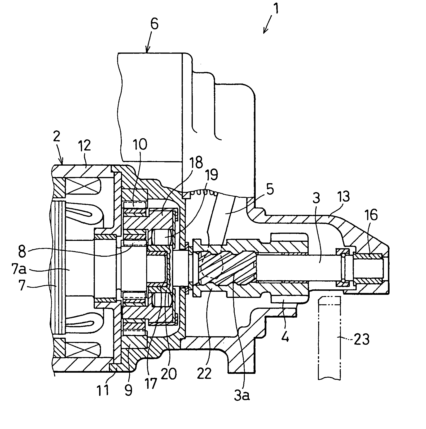
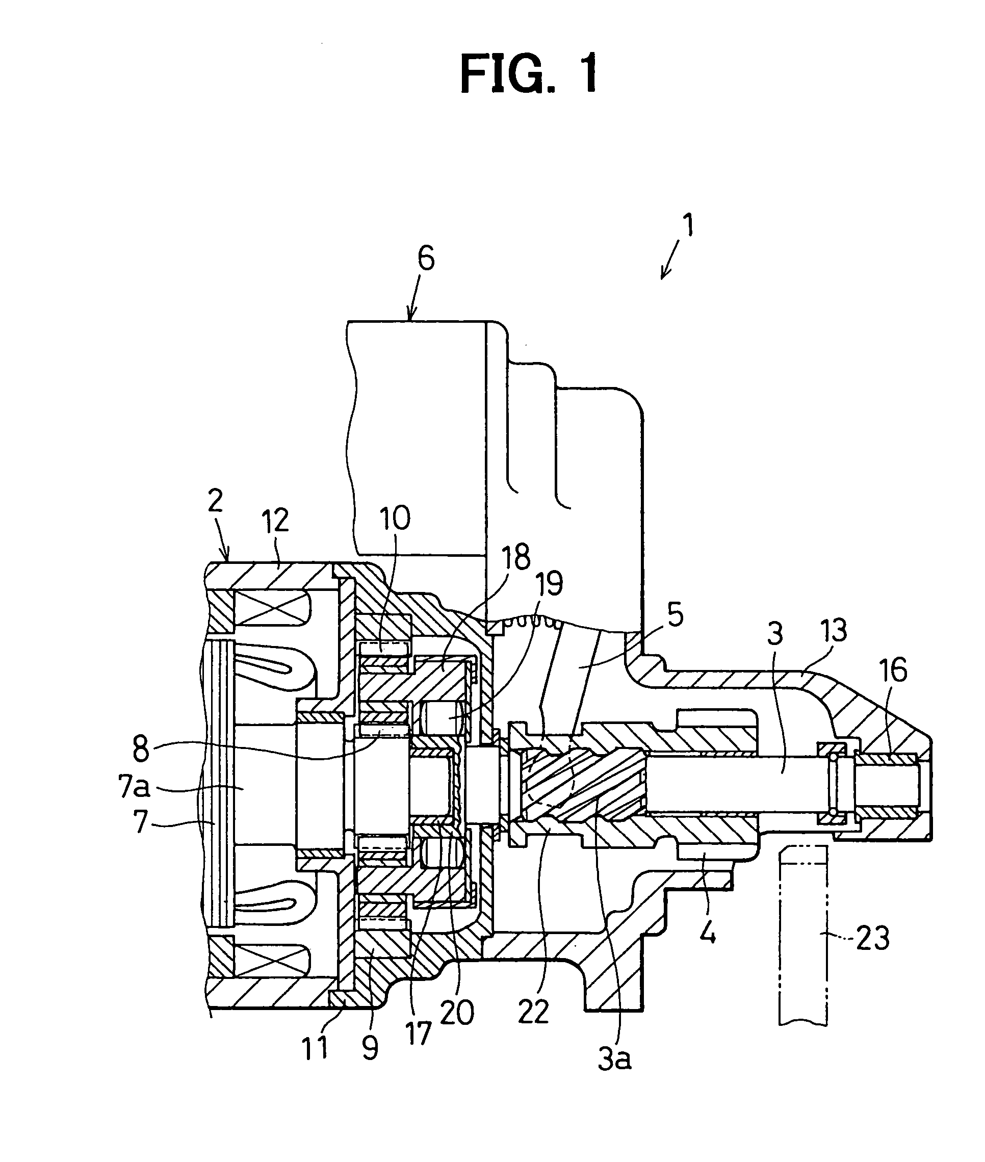
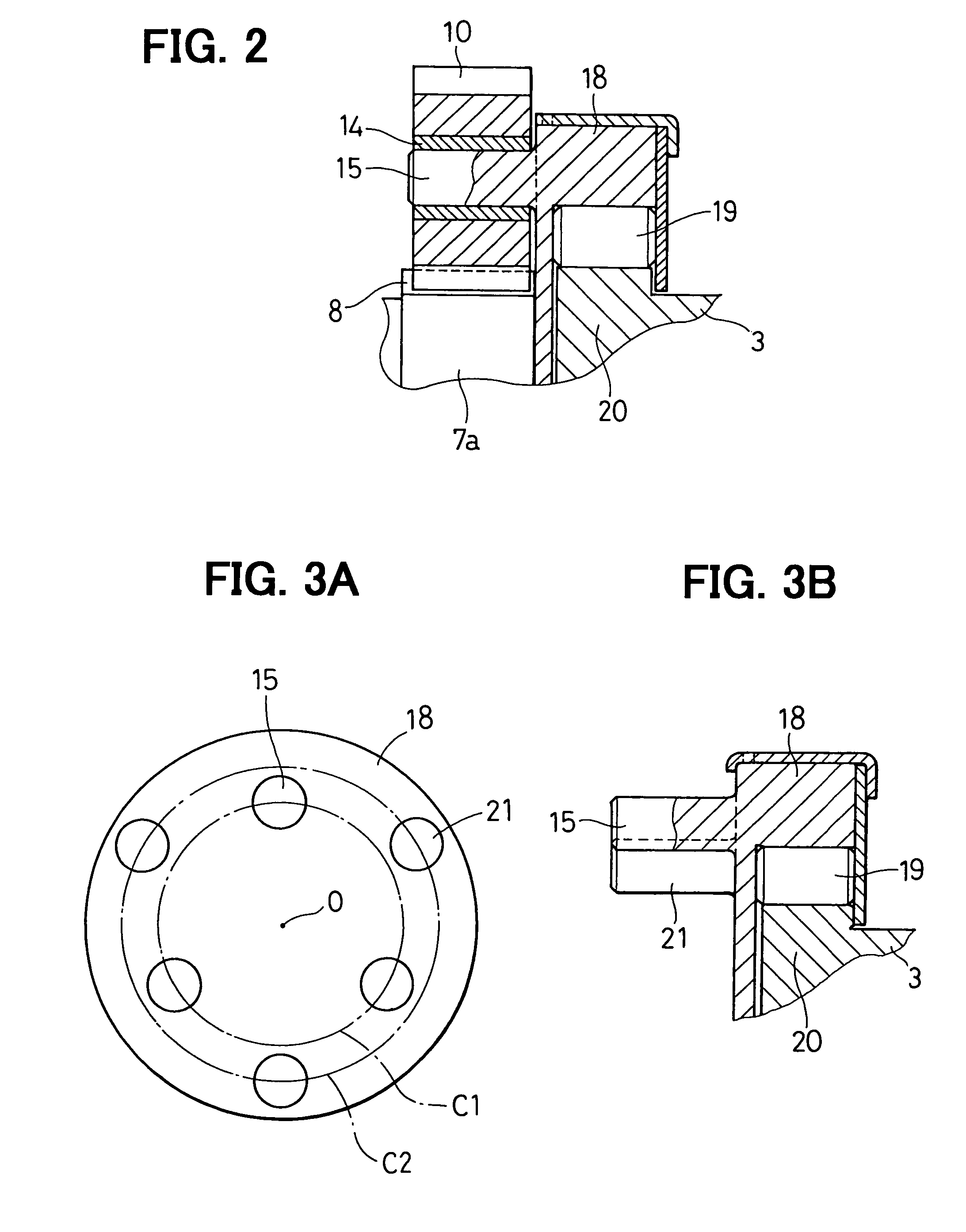
[0008]According to the present invention, a starter has a planetary reduction gear device that reduces a rotation speed of a motor. The planetary reduction gear device has a planet carrier forming gear shafts projecting from the surface of the planet carrier and a plurality of planetary gears rotatably supported by the gear shafts. The planet carrier further forms projections projecting in a direction same as the gear shafts.
[0009]Accordingly, since the predetermined projections are integrally formed into the planet carrier, stress of a die while producing the planet carrier such as by cold forging is reduced. Therefore, the life of the die is improved. As a result, manufacturing costs can be reduced.

Problems solved by technology

Therefore, specifications of planetary gears, which can be mounted on the planet carrier, are limited.
That is, it is difficult to change the speed reduction ratio by mounting planetary gears having different gear specification to the same planet carrier.
As a result, the die is likely to be broken.

Method used


Image

  • Starter with planetary reduction gear device
  • Starter with planetary reduction gear device
  • Starter with planetary reduction gear device

Examples


second embodiment

(Second Embodiment)

[0049]In the second embodiment, as shown in FIG. 5, each of the waste shafts 21 has a polygonal-shaped cross-section such as a triangle-shaped cross-section, instead of the circular-shaped cross-section of the first embodiment. The cross-sectional shape of the waste shaft 21 is not limited to the circular shape.

[0050]When the waste shafts 21 are used as the secondary gear shafts, the external shapes of the waste shafts 21 are processed so that the bearings can engage with the waste shafts 21. Alternatively, the bearings are driven into the waste shafts 21 and the external shapes of the bearings are shaped into substantially cylindrical shapes. The gear shafts 15 and the waste shafts 21 are integrally formed into the clutch outer portion 18 and arranged in a manner similar to the first embodiment.

third embodiment

(Third Embodiment)

[0051]In the third embodiment, the planet carrier and the clutch outer portion of the one-way clutch are separately provided.

[0052]As shown in FIG. 6, the planetary reduction gear device has a planet carrier 24 into which the gear shafts 15 and waste shafts (not shown) are integrally formed. A clutch outer portion 18a, which functions in a manner similar to the clutch outer portion 18 of the first embodiment, is provided as a separate part from the planet carrier 24. The clutch outer portion 18a and the planet carrier 24 are connected to each other in a relative rotation restricted manner. That is, the clutch outer portion 18a rotates with the planet carrier 24.

[0053]Also in the third embodiment, the gear shafts 15 and the waste shafts are integrally formed into the planet carrier 24 and arranged in a manner similar to the first embodiment. Therefore, the waste shafts can be used as the secondary gear shafts. Similar to the first embodiment, the speed reduction rat...

fourth embodiment

(Fourth Embodiment)

[0054]As shown in FIG. 7, the starter 1 of the fourth embodiment has the planet carrier 24 into which the gear shafts 15 and the waste shafts (not shown) are integrally formed in a manner similar to the first embodiment. Further, the planet carrier 24 is provided as the part of the output shaft 3. A one-way clutch 25 is arranged movable along the output shaft 3 with the pinion gear 4.

[0055]Also in the fourth embodiment, since the gear shaft 15 and the waste shafts are integrally formed into the planet carrier 24, the waste shafts are used as the secondary shafts. Therefore, the speed reduction ratio can be changed by mounting the planetary gears having different gear specification to the secondary shafts.


PUM


Abstract

In a planetary reduction gear device of a starter, a planet carrier forms gear shafts and planetary gears are rotatably supported by the gear shafts through bearings. The planet carrier further forms waste shafts projecting in a direction same as that of the gear shafts. The waste shafts are arranged on a circle having a center coincident with a rotation axis of the clutch outer portion at regular intervals in a circumferential direction. The circle on which the waste shafts are arranged has a diameter different from that of a circle on which the gear shafts are arranged. A speed reduction ratio can be changed by mounting planetary. gears having a gear specification different from that of the planetary gears supported on the gear shafts on the waste shafts. The planet carrier can be integrally formed with a clutch outer portion of a one-way clutch.

Description

CROSS REFERENCE TO RELATED APPLICATION[0001]This application is based on Japanese Patent Application No. 2003-95880 filed on Mar. 31, 2003, the disclosure of which is incorporated herein by reference.FIELD OF THE INVENTION[0002]The present invention relates to a starter having a planetary reduction gear device.BACKGROUND OF THE INVENTION[0003]Generally, a planetary reduction gear device used in a starter is constructed of a sun gear, an internal gear and planetary gears. The sun gear is provided on a rotation shaft of a motor. The internal gear is in a form of ring and is arranged concentric with the sun gear. The planetary gears are rotatably supported by gear shafts and engage with the sun gear and the internal gear.[0004]When the sun gear rotates with the motor, the planetary gears rotate and revolute. The revolution movement of the planetary gears are transmitted to a planet carrier through the gear shafts, thereby to rotate the planet carrier. Accordingly, the rotation force of...

Claims


Application Information

Patent Timeline
Patent Type & Authority Patents(United States)
IPC IPC(8): F16H48/06F02N15/02F02N15/04F02N15/06F16H1/28
CPCF02N15/023F02N15/046F02N15/066F02N15/067F16H1/28F16H57/082Y10T74/137
Inventor MURATA, MITSUHIROSHIGA, TSUTOMUOHMI, MASANORIMORITA, MASAHIRO
Owner DENSO CORP
Learn More