Injection molded centrifugal air impeller

a centrifugal air and injection molding technology, applied in the direction of propulsive elements, vessel construction, marine propulsion, etc., can solve problems such as reducing efficiency, and achieve the effect of reducing the likelihood of flashing and minimizing mold wear

Inactive Publication Date: 2005-05-05
TORRINGTON RES CO ASSIGNEE +1
View PDF1 Cites 4 Cited by
  • Summary
  • Abstract
  • Description
  • Claims
  • Application Information

AI Technical Summary

Benefits of technology

[0007] More particularly, the impeller design accommodates forming of an inner edge portion of each blade in the core of the mold and forming of an outer edge por...

Problems solved by technology

Leakage flow around the blade ends at the inlet is inhibited and this enhances impeller performance High v...

Method used


Image

  • Injection molded centrifugal air impeller
  • Injection molded centrifugal air impeller
  • Injection molded centrifugal air impeller

Examples


Embodiment Construction

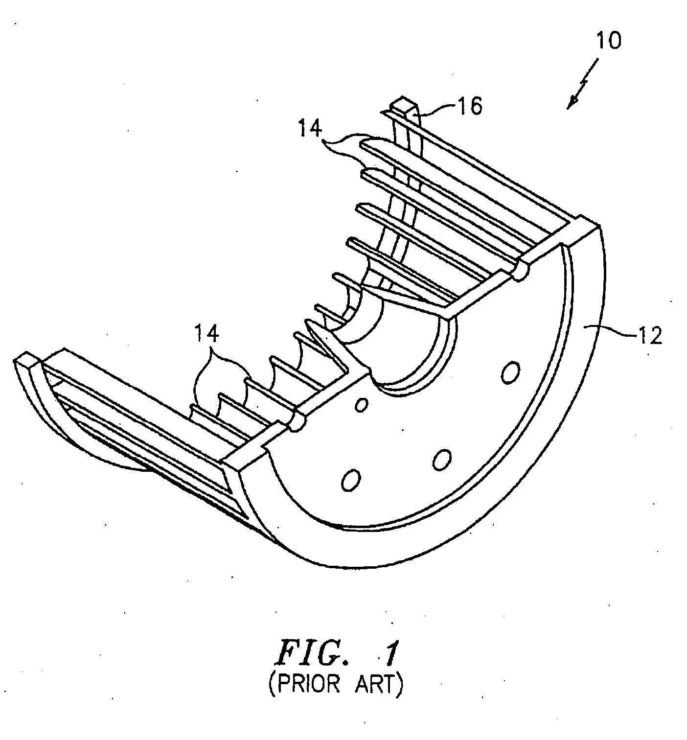
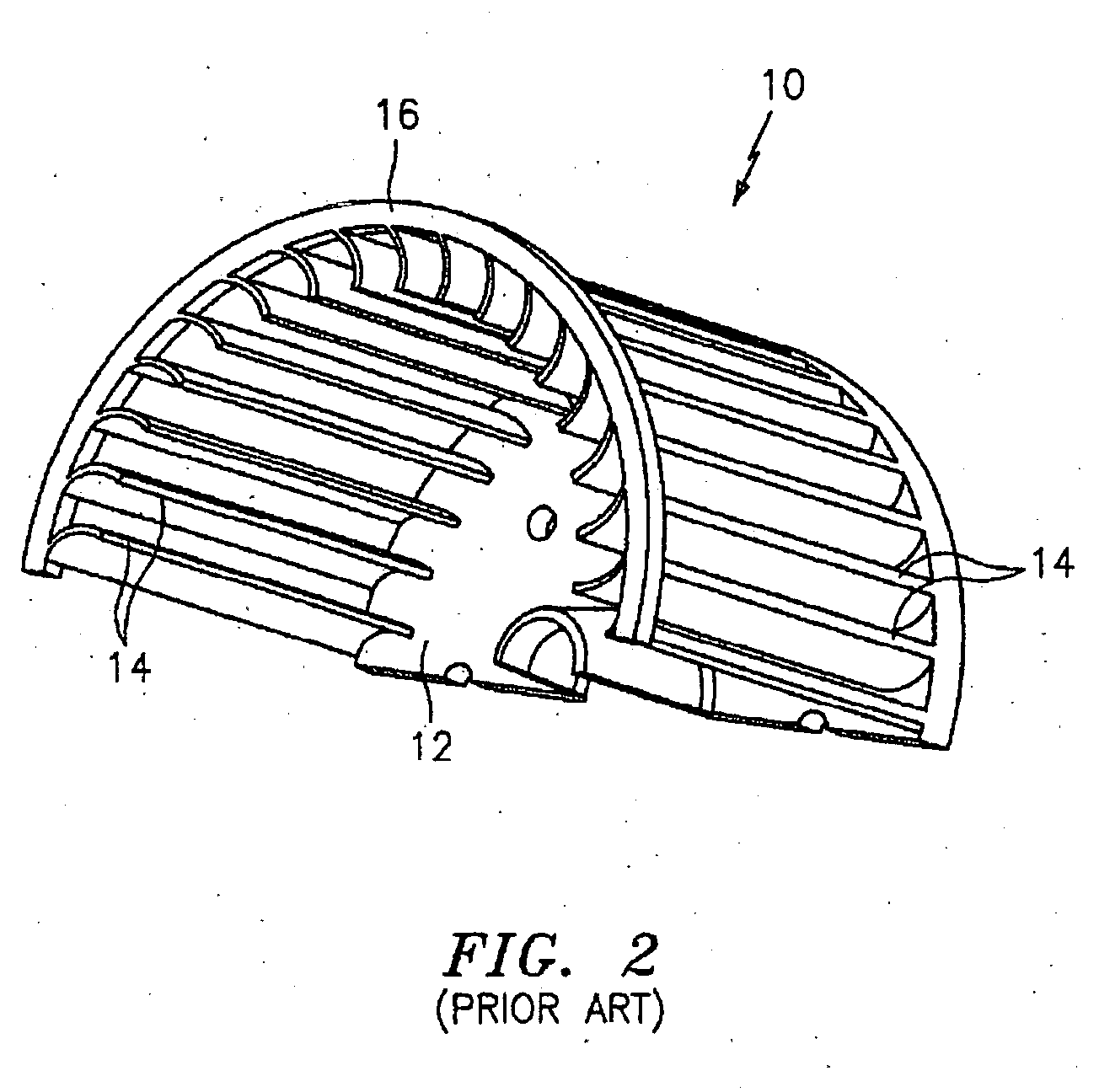
[0013] Referring initially to FIGS. 1 and 2, a prior art impeller indicated generally at 10 has a back plate 12, a plurality of circumaxially arranged air moving blades 14,14 integral with the back plate 12, and an end ring 16 integral with the blades at an end thereof opposite the back plate. The outer diameter of the back plate coincides with that of the blades and the inner diameter of the end ring coincides with the outer diameter of the blades. Thus, it will be apparent that the cavity of the mold forms only the inlet ring and the core of the mold forms the back plate and blades. It will also be apparent that the shut off and parting line must reside along the outer edges of the blades the aforementioned attendant disadvantages being encountered.

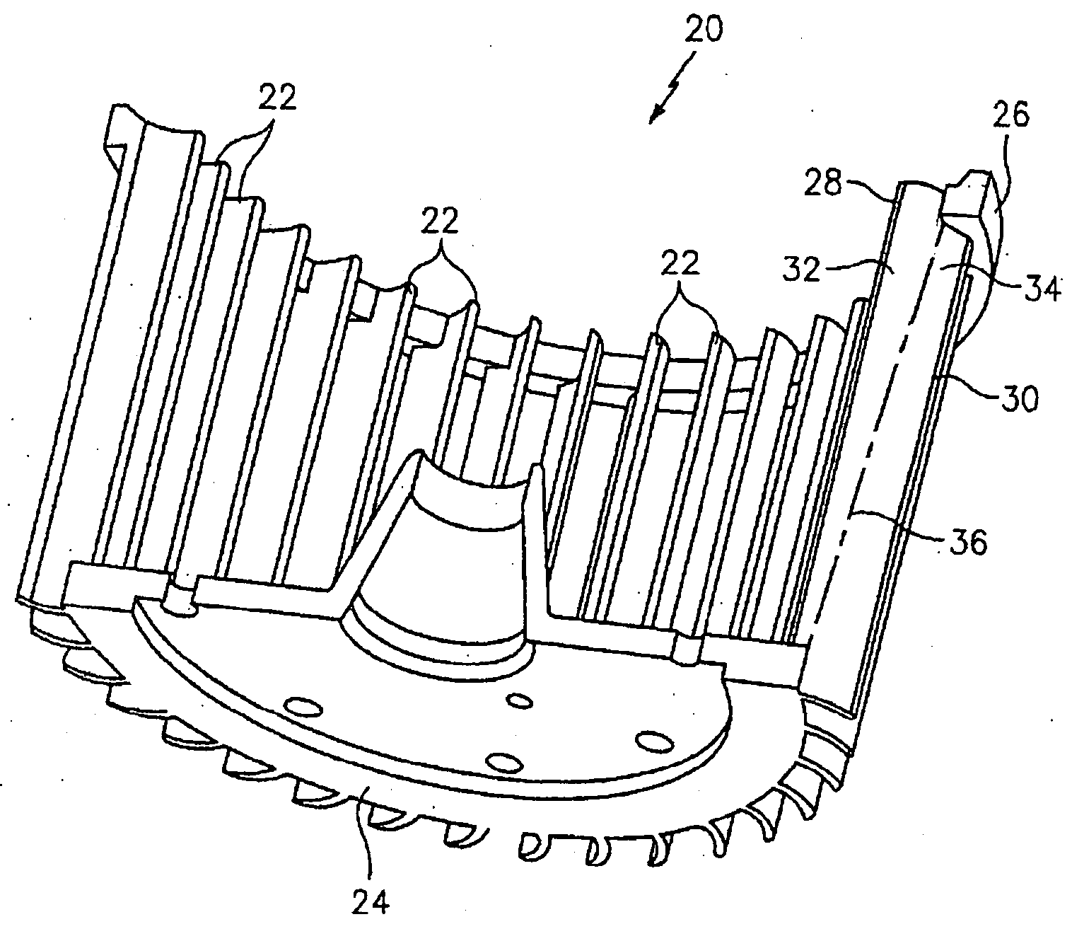
[0014] The improved impeller shown in FIG. 3 at 20 has a plurality of blades 22,22, a back plate 24, and an end ring 26. Each blade 22 has inner and outer edges 28 and 30 and adjacent inner and outer elongated portions 32 and 34 which ...


PUM

PropertyMeasurementUnit
Fractionaaaaaaaaaa
Fractionaaaaaaaaaa
Diameteraaaaaaaaaa

Abstract

A centrifugal air impeller designed for injection molding has a mold parting line extending intermediate the sides of the blades thus permitting optimum configurations of the inner and outer blade edges and enhanced impeller performance. The impeller inlet ring has an inner diameter less than that of the outer edges of the blades and an outer diameter greater than the outer diameter of the blades. The backplate has a diameter greater than that of the inner diameter of the blades.

Description

[0001] (This application claims the benefit of provisional application Serial Number [not received to date] filed on Aug. 29, 2003.) BACKGROUND OF INVENTION [0002] Injection molded centrifugal air impellers with forwardly curved blades have an air flow pattern which is three dimensional. In the plane of rotation, there is a circulation that flows outwardly through the blades for approximately three hundred degrees (300°) of rotation. After passing the eye of circulation the flow reverses direction and passes back through the blades. Air flows into the blower inlet substantially along the section where the main circulation is outward. Although some air may flow out of the inlet along the section where the main circulation is inward, there is a net through flow of air out the blower discharge. The center of the main circulation is located near the inner edge of the impeller blades at the point where the flow reverses from outward to inward. Since the main circulation is larger than th...

Claims


Application Information

Patent Timeline
IPC IPC(8): B29C33/00B29C45/00B63H1/16F04D29/02F04D29/28
CPCB29C33/005B29C45/00F04D29/283F04D29/023B29L2031/08F05D2230/53F05D2300/43
Inventor O'CONNOR, JOHN F. JR.
Owner TORRINGTON RES CO ASSIGNEE
Why Eureka
Try Eureka