Manual self-centering clamp plate

A self-centering, splint technology, applied in the direction of positioning device, feeding device, storage device, etc., can solve the problem of not having fast clamping bar material, complex and other problems

Inactive Publication Date: 2015-04-01
CHONGQING ZETIAN AUTO PARTS
View PDF9 Cites 1 Cited by
  • Summary
  • Abstract
  • Description
  • Claims
  • Application Information

AI Technical Summary

Problems solved by technology

[0003] The control of the car is mainly realized by the steering rod and the steering wheel. At present, the steering rod is made of bar material, and the bar material needs to be straightened many times during the production and processing process, but the fixture used for bar material alignment is currently The structure is usually complex and does not have the function of quickly clamping the bar

Method used


Image

  • Manual self-centering clamp plate
  • Manual self-centering clamp plate
  • Manual self-centering clamp plate

Examples


Embodiment 1

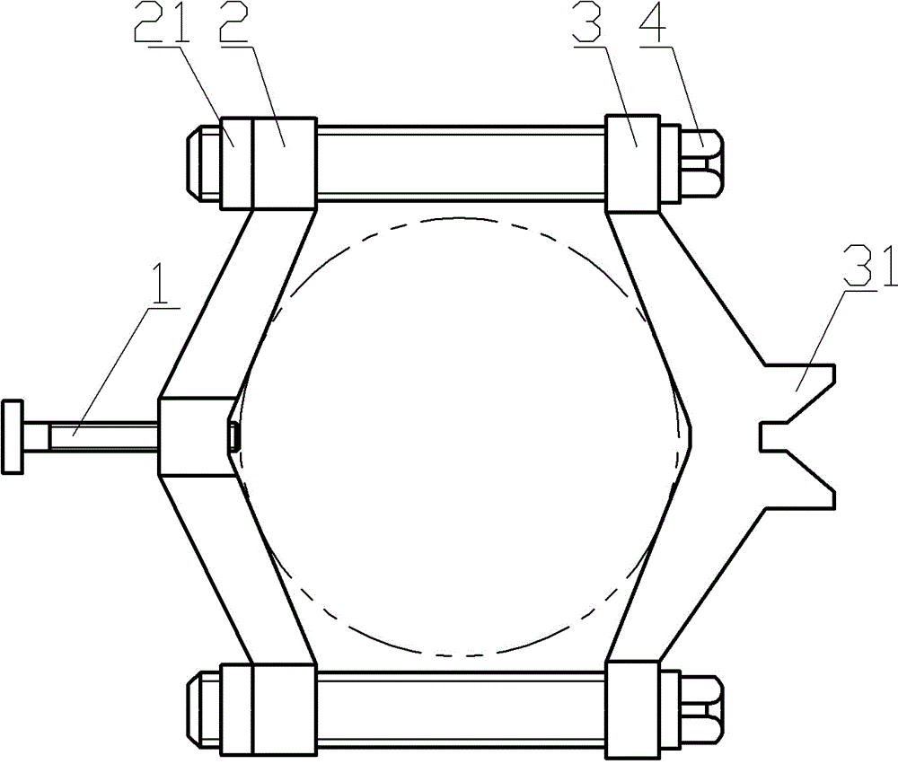
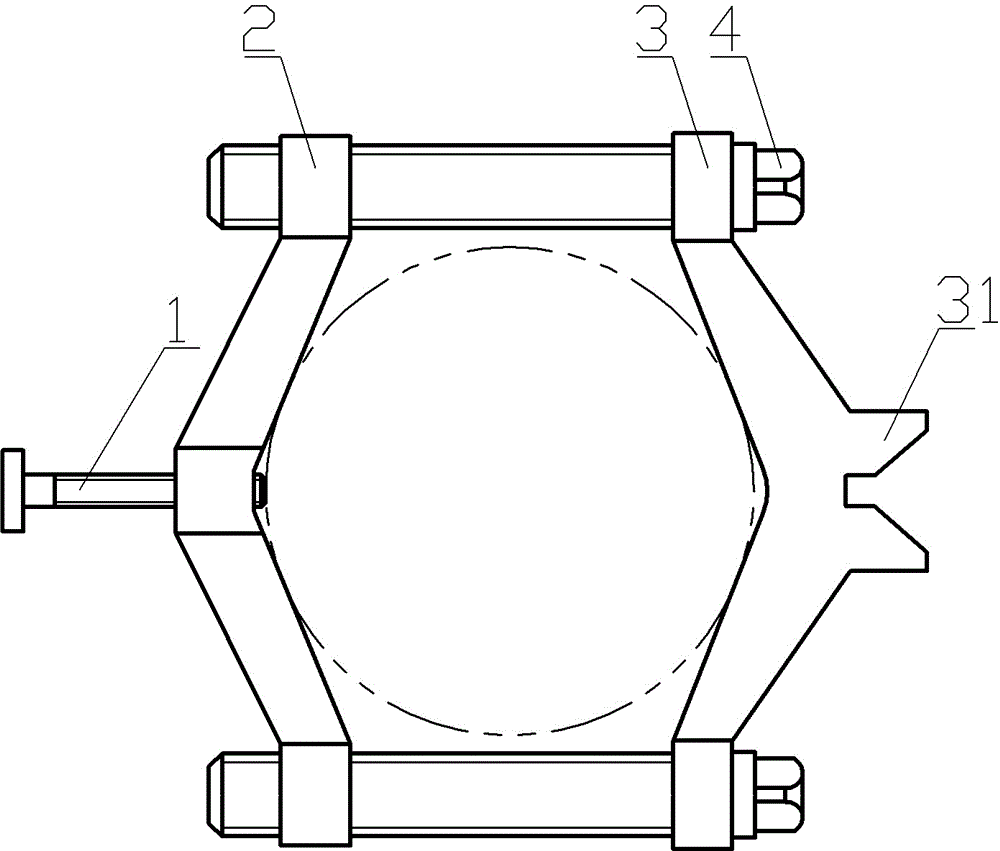
[0017] Embodiment one is basically as attached figure 1 , figure 2 As shown: the manual self-centering splint includes upper bolt 3, lower bolt, left splint 2, right splint 3 and jacking screw 1; the upper bolt and lower bolt are arranged side by side, and it is best to keep it horizontal, and the upper end of the right splint is set on the upper bolt. The lower end of the right clamping plate is covered with the lower bolt, and the right clamping plate can slide on the upper bolt and the lower bolt. One side of the right clamping plate is a V-shaped positioning surface, and the other side of the right clamping plate is a small V-shaped block portion 31; The upper end of the splint and the lower end of the left splint are respectively socketed with upper bolts and lower bolts. Nuts 21 are provided on the upper end of the left splint and the outer side of the lower end of the left splint. Good bar material, the middle part of the left splint is threaded to connect the jacking...

Embodiment 2

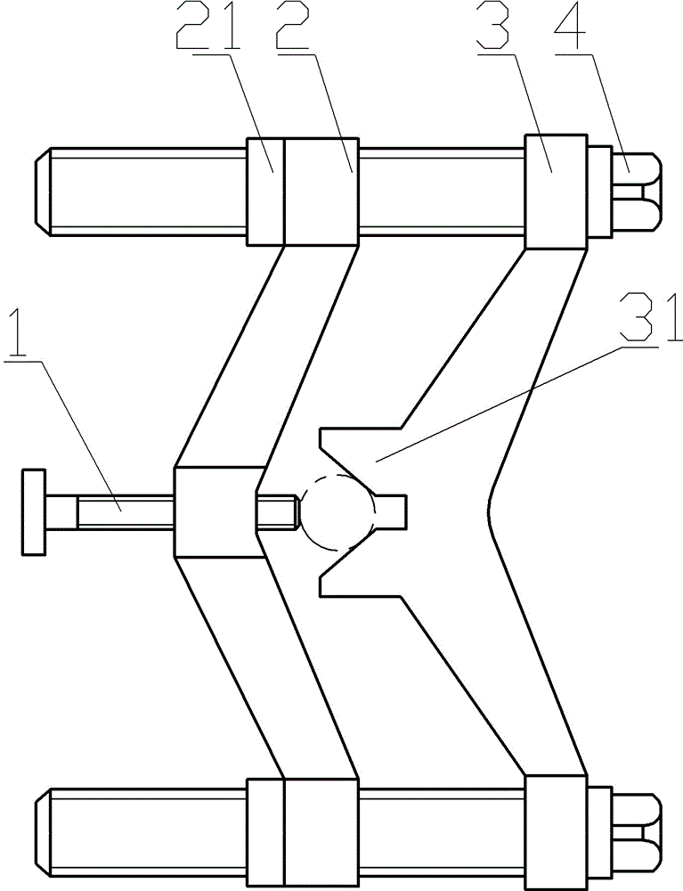
[0020] Such as image 3 , Figure 4 As shown, the difference between the second embodiment and the first embodiment is only that the nut 21 is not included, the upper end of the left splint is threaded with the upper bolt; the lower end of the left splint is threaded with the lower bolt. The lower bolt can lock the upper end of the left splint and the lower end of the left splint, thereby clamping and fixing the bar.


PUM


Abstract

The invention discloses a manual self-centering clamp plate which comprises an upper bolt, a lower bolt, a left clamp plate, a right clamp plate and a set screw. The upper bolt and the lower bolt are distributed side by side, the upper end of the right clamp plate sleeves the upper bolt, the lower end of the right clamp plate sleeves the lower bolt, a V-shaped positioning surface is arranged on one side of the right clamp plate, a small V-shaped block is arranged on the other side of the right clamp plate, the left clamp plate is V-shaped, the upper end of the left clamp plate can be locked with the upper bolt, the lower end of the left clamp plate can be locked with the lower bolt, and the middle of the left clamp plate is connected with the set screw in a threaded manner. The manual self-centering clamp plate is simple in structure, easy to operate and conveniently and rapidly straightened, automobile steering yoke rods can be rapidly clamped, and cost is reduced.

Description

technical field [0001] The invention relates to the technical field of automobile steering rod production, in particular to a manual self-centering splint. Background technique [0002] Automobile refers to the means of transportation powered by engines using gasoline, diesel, natural gas and other fuels or new energy sources such as batteries and solar energy. A vehicle that generally has four or more wheels and can travel on land without relying on rails or wires. [0003] The control of the car is mainly realized by the steering rod and the steering wheel. At present, the steering rod is made of bar material, and the bar material needs to be straightened many times during the production and processing process, but the fixture used for bar material alignment is currently The structure is usually complicated, and it does not have the function of fast clamping bar. Contents of the invention [0004] The present invention intends to provide a manual self-centering splint ...

Claims


Application Information

Patent Timeline
Patent Type & Authority Applications(China)
IPC IPC(8): B21D43/00B21D3/16
CPCB21D43/003B21D3/16
Inventor 黄忠泽
Owner CHONGQING ZETIAN AUTO PARTS
Why Eureka
Try Eureka