Multi-point pressurizing type hydraulic die forging method

A liquid die forging and multi-point technology, which is applied in the field of liquid die forging and liquid die forging of metal materials, can solve the problems that it is difficult to produce complex workpieces and cannot realize multi-point pressure, so as to achieve good structure and performance uniformity and high workpiece quality. Stable and reliable, wide range of effects

Active Publication Date: 2015-04-01
BEIJING JIAOTONG UNIV
View PDF5 Cites 13 Cited by
  • Summary
  • Abstract
  • Description
  • Claims
  • Application Information

AI Technical Summary

Problems solved by technology

[0005] The purpose of the present invention is to provide a multi-point pressurized liquid die forging method for the problem that the existing liquid die forging technology cannot realize multi-point pressurization and it is difficult to produce complex workpieces with multiple hot joint positions

Method used


Image

  • Multi-point pressurizing type hydraulic die forging method
  • Multi-point pressurizing type hydraulic die forging method
  • Multi-point pressurizing type hydraulic die forging method

Examples


Embodiment 1

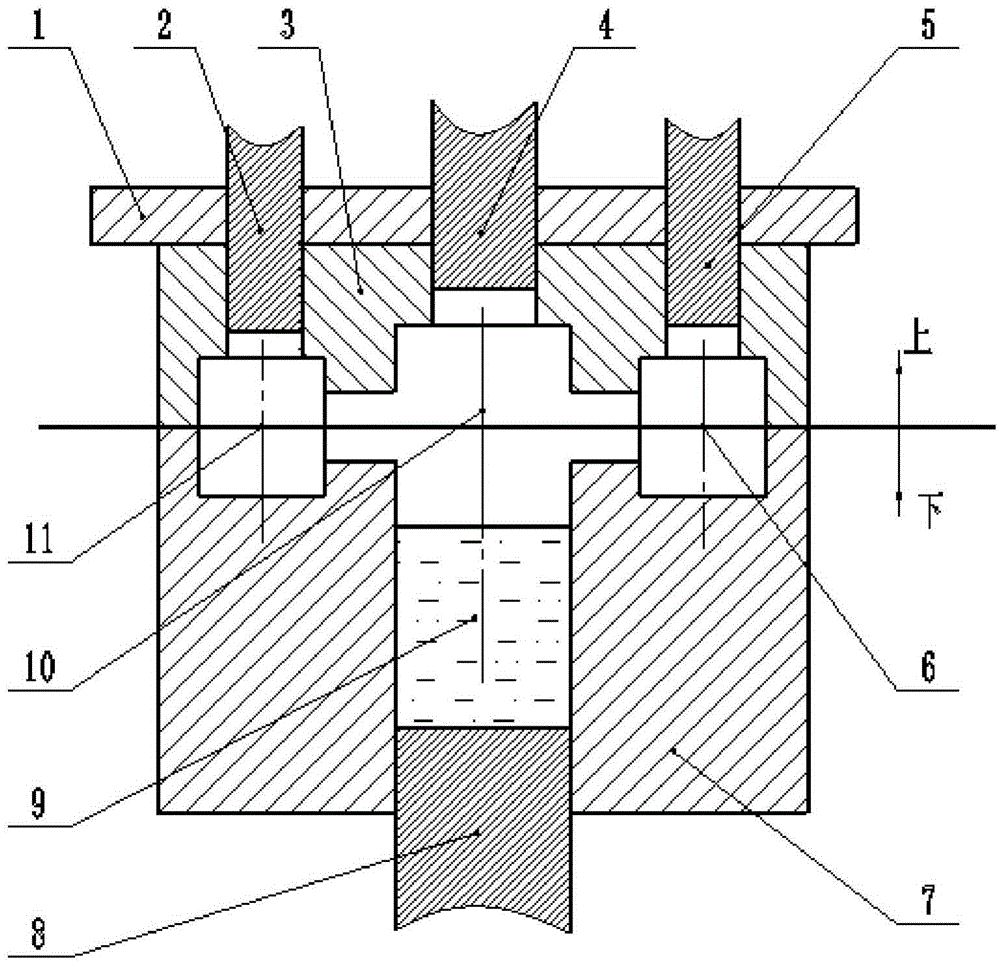
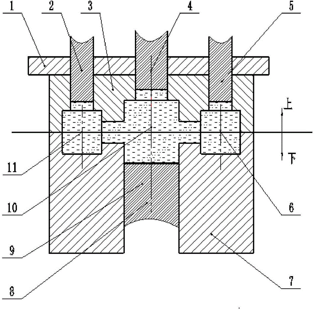
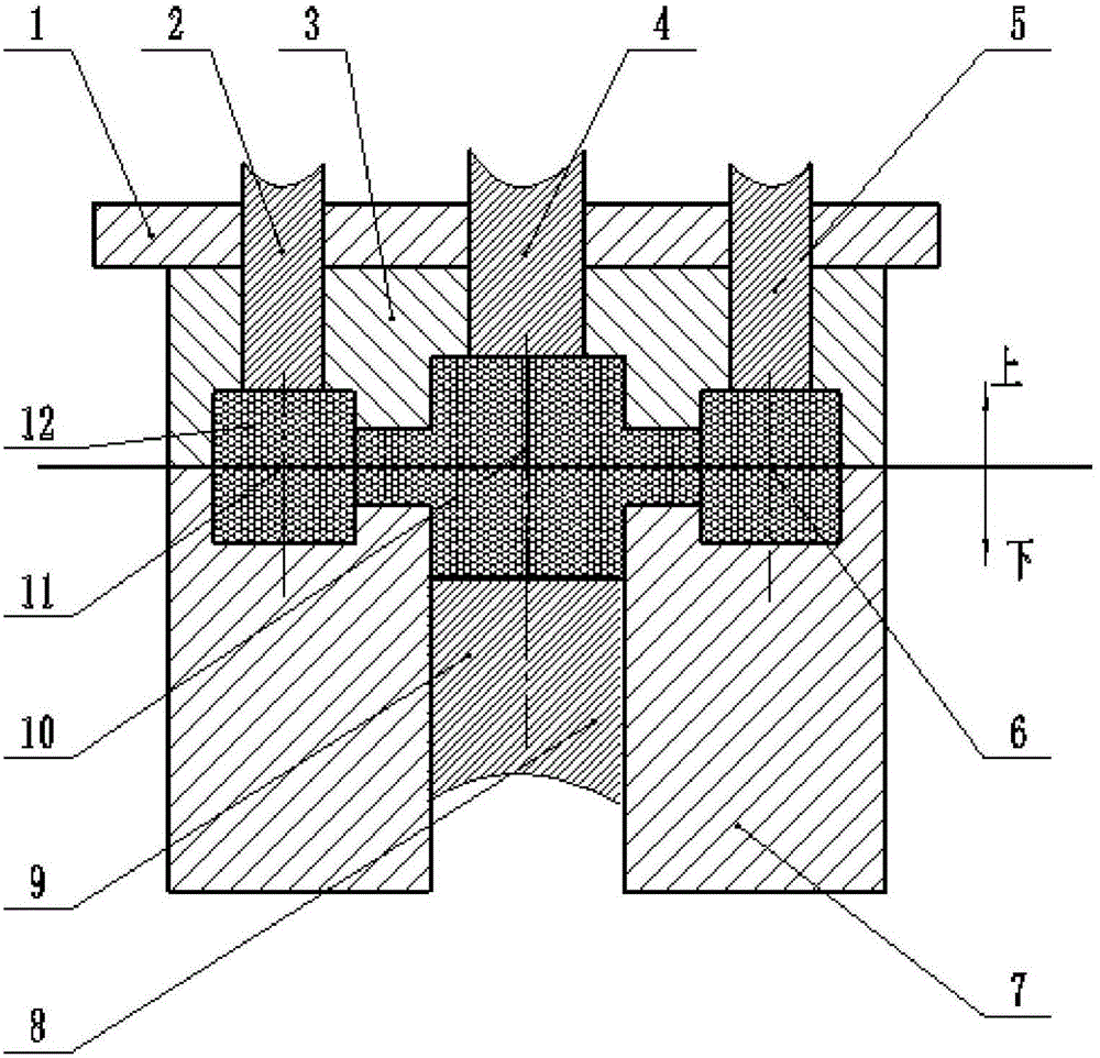
[0041] The workpiece of the embodiment of the present invention has three hot joint positions, and the mold for liquid die forging (referred to as liquid forging) of the workpiece at least includes a clamping indenter, a feeding indenter, an upper die, a lower die, a mold cavity, a lower press Head, pressure chamber. This implementation provides a 4-point pressurized liquid die forging method suitable for this workpiece, including the following five key steps, combined with Figure 1 to Figure 3 The mold clamping diagram of each stage in the liquid forging process shown is as follows:

[0042](1) Adjust the position and stroke of the feeding head: adjust the position and stroke of the first feeding head 2, the second feeding head 4, and the third feeding head 5, so that the first hot joint position 11, The second thermal joint position 10 and the third thermal joint position 6 each have a corresponding feeding head. The stroke of each feeding head is twice the compact compres...

Embodiment 2

[0049] The workpiece of the embodiment of the present invention is a frame-like part with 6 hot joint positions, and the mold for liquid forging the workpiece includes at least a clamping ram, a feeding ram, an upper die, a lower die, a die cavity, and a lower die. Head, pressure chamber. This implementation provides a 7-point pressurized liquid die forging method suitable for this workpiece, including the following five key steps, described as follows:

[0050] (1) Adjust the position and stroke of the feeding head: adjust the position and stroke of the 6 feeding heads, so that each hot spot has a corresponding feeding head, and each feeding head The stroke is 6 times the compact compression amount of each hot joint position, and the pressure end surface area of ​​each feeding pressure head is equal to 0.75 times the cross-sectional area of ​​the corresponding hot joint position;

[0051] (2) Pouring: The alloy liquid whose temperature is higher than the liquidus temperature...

Embodiment 3

[0058] The workpiece in the embodiment of the present invention is a rod part with 7 hot joint positions. The mold for liquid forging the workpiece includes at least a clamping ram, a feeding ram, an upper die, a lower die, a mold cavity, a lower press Head, pressure chamber. This implementation provides an 8-point pressurized liquid die forging method suitable for this workpiece, including the following five key steps, described as follows:

[0059] (1) Adjust the position and stroke of the feeding head: adjust the position and stroke of the 7 feeding heads so that each hot spot has a corresponding feeding head. The stroke is 10 times the compact compression amount of each hot joint position, and the pressure end surface area of ​​each feeding pressure head is equal to 1 time the cross-sectional area of ​​the corresponding hot joint position;

[0060] (2) Pouring: The alloy liquid whose temperature is 100°C higher than the liquidus temperature of the liquid forging alloy is ...


PUM


Abstract

The invention discloses a multi-point pressurizing type hydraulic die forging method. The method comprises the steps of S1, adjusting the position and travel of each feeding pressing head to make ensure the feeding pressing head is at each corresponding hot spot position of a component and the travel of each feeding head is more than the density compact compression amount of the corresponding hot spot position; S2, pouring molten liquid under a temperature exceeding the temperature of liquid phase line of alloy into a die cavity or a pressing cavity which communicates with the die cavity; S2, fast closing the die, and applying a locking force to lock the die; S4, pressurizing the molten alloy to enable flowing and filling in the whole die cavity; S5, sequentially or synchronously applying a force to each hot spot position of the component and the pressing cavity to enable the molten alloy at the hot spot position to be fast solidified and subjected to rheological feeding until completely solidifying; S6, releasing all pressures, opening the die and removing the component. With the adoption of the method, the problem of liquid forging of large complex component can be effectively solved; the method has the advantages of being small in investment, free of shrinkage defect in the component, stable in product quality, and wide in applicable scope.

Description

technical field [0001] The invention relates to a liquid die forging method, in particular to a multi-point pressurized liquid die forging method, which is used for liquid die forging of large and complex pieces of metal materials, and belongs to the field of liquid die forging of metal materials. Background technique [0002] Liquid die forging is a new technology of material liquid forming that is being popularized and applied. It is characterized in that the liquid metal poured into the cavity is directly or indirectly pressurized to make it solidify and form under pressure. Liquid die forging in the prior art all assumes that liquid metal, like water, can transmit pressure at an equivalent value indefinitely, so generally there is only one pressurization position. The liquid die forging in which the pressure is directly applied to the workpiece is called direct liquid forging, and the liquid die forging in which the pressure is first applied outside the workpiece (usuall...

Claims


Application Information

Patent Timeline
Patent Type & Authority Applications(China)
IPC IPC(8): B22D18/02
CPCB22D18/02
Inventor 邢书明鲍培玮郭莉军李兰敖晓辉王井铃邱常明
Owner BEIJING JIAOTONG UNIV
Why Eureka
Try Eureka