Laser equipment and laser scanning galvanometer array calibrating method

A technology of scanning galvanometer and laser equipment, which is applied in the direction of laser welding equipment, welding equipment, metal processing equipment, etc., can solve the problems of not being able to realize large-area scanning and marking, reduce manufacturing accuracy requirements, and ensure operation quality Effect

Active Publication Date: 2015-04-01
HANS LASER TECH IND GRP CO LTD +1
View PDF8 Cites 36 Cited by
  • Summary
  • Abstract
  • Description
  • Claims
  • Application Information

AI Technical Summary

Problems solved by technology

[0002] Traditional laser equipment, such as laser marking machines, have a fixed scanning range of the galvanometer, which cannot scan and mark large areas

Method used


Image

  • Laser equipment and laser scanning galvanometer array calibrating method
  • Laser equipment and laser scanning galvanometer array calibrating method
  • Laser equipment and laser scanning galvanometer array calibrating method

Examples


Embodiment Construction

[0025] Now in conjunction with the accompanying drawings, the preferred embodiments of the present invention will be described in detail.

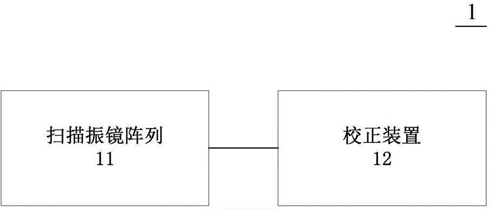
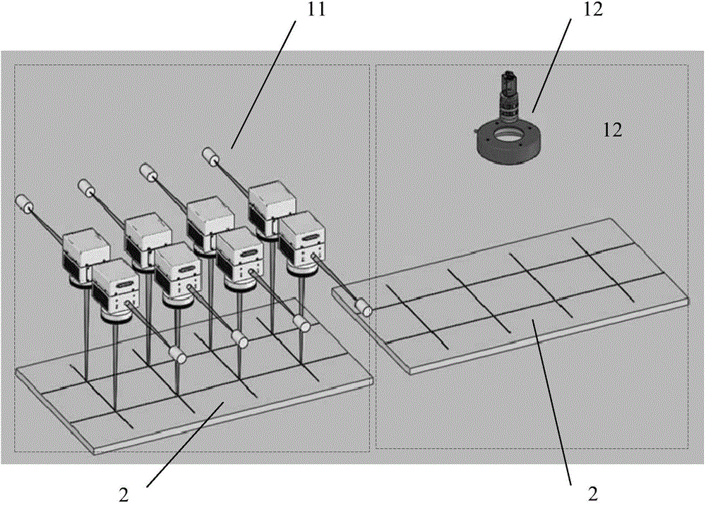
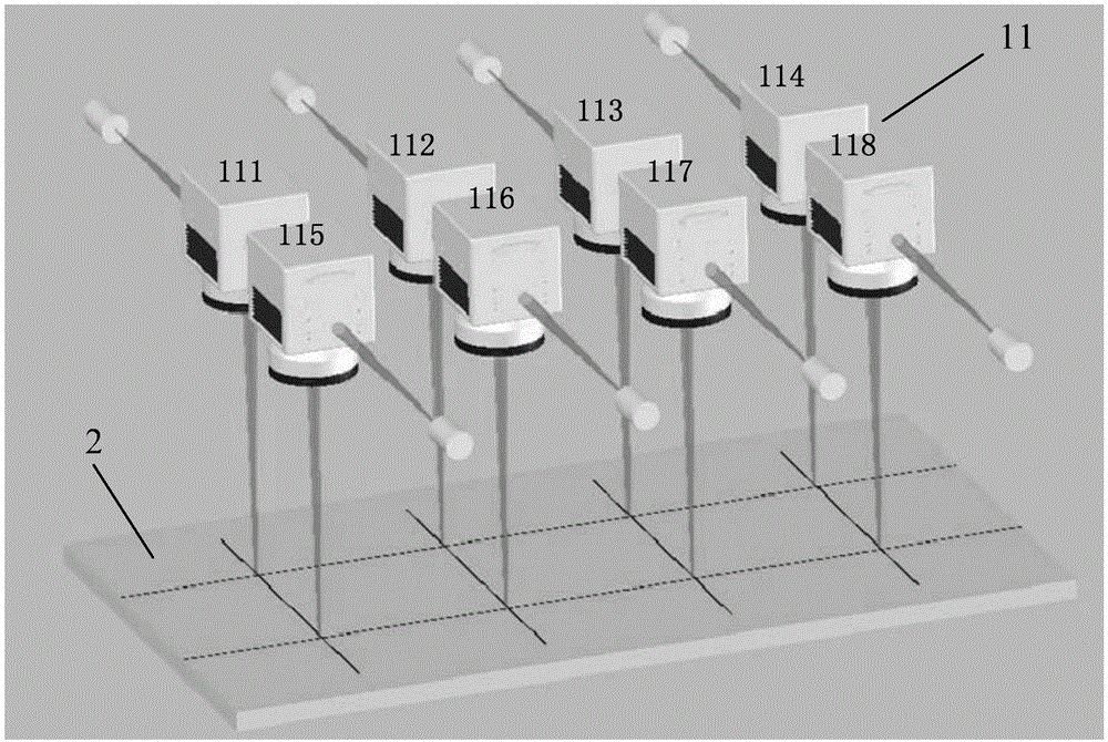
[0026] figure 1 It is a schematic block diagram of the laser device of the present invention. figure 2 It is a structural representation of the laser equipment of the present invention. Figure 3A It is a structural representation of the scanning galvanometer array in the laser equipment of the present invention, Figure 3B It is a structural representation of the correction device in the laser equipment of the present invention. Such as Figures 1 to 3B As shown, the present invention proposes a laser device, which generally includes a scanning galvanometer array 11 and a calibration device 12 matched with the scanning galvanometer array 11 . In this embodiment, the scanning galvanometer array 11 has a 2×4 structure, including a first scanning galvanometer 111, a second scanning galvanometer 112, a third scanning galvanometer 113, an...


PUM


Abstract

The invention relates to the field of laser equipment, in particular to laser equipment and a laser scanning galvanometer array calibrating method. The laser scanning galvanometer array calibrating method includes steps of acquiring images corresponding to operations of a laser scanning galvanometer array by a calibrator, processing the images by the calibrator so as to obtain calibration values of various scanning galvanometer; generating actual scanning positions by the scanning galvanometer so as to scan according to the calibration values. By the laser equipment and the laser scanning galvanometer array calibrating method, operation quality in a large operation area is ensured under the condition that manufacturing accuracy requirement of the equipment can be reduced.

Description

technical field [0001] The invention relates to a laser device, in particular to the correction of a laser scanning vibrating mirror array of the laser device. Background technique [0002] Traditional laser equipment, such as laser marking machines, have a fixed scanning range of the galvanometer, which cannot scan and mark large areas. The existing laser equipment that can realize large-area operations is realized by using the arrangement and combination of scanning galvanometers. In order to ensure the quality of work in large-area operation areas, the manufacturing accuracy of this kind of laser equipment is very high. . The reason why high manufacturing precision is required is that once a certain degree of positional deviation occurs between the galvanometers in the scanning galvanometer group due to factors such as machining, the processed products in this case , For example, the marked shape or label will be distorted. For example, when a series of parallel lines a...

Claims


Application Information

Patent Timeline
Patent Type & Authority Applications(China)
IPC IPC(8): B23K26/035B23K26/082
Inventor 周蕾李玉廷王光能舒远米野丁兵高云峰
Owner HANS LASER TECH IND GRP CO LTD
Why Eureka
Try Eureka