Automatic transmission line pulse test system
A transmission line pulse and test system technology, which is applied in the direction of electronic circuit testing, measuring electricity, measuring devices, etc., can solve the problem of high cost
- Summary
- Abstract
- Description
- Claims
- Application Information
AI Technical Summary
Problems solved by technology
Method used
Image
Examples
Embodiment Construction
[0012] The present invention will be described in further detail below in conjunction with the embodiments and accompanying drawings, but the embodiments of the present invention are not limited thereto.
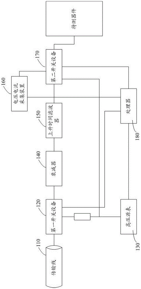
[0013] Such as figure 1 As shown, it is a schematic structural diagram of Embodiment 1 of the automatic transmission line pulse test system of the present invention, including: a transmission line 110, a first switching device 120, a high voltage source meter 130, an attenuator 140, a rise time filter 150, a voltage and current acquisition device 160, a second switching device 170, a processor 180;
[0014] The transmission line 110 is respectively connected to the attenuator 140 and the high voltage source meter 130 through the first switching device 120, the attenuator 140 is connected to the rise time filter 150, the rise time filter 150, the voltage and current acquisition device 160 and the high voltage source meter 130 are respectively The device under test is connect...
PUM
 Abstract
Description
Claims
Application Information
 - R&D
- Intellectual Property
- Life Sciences
- Materials
- Tech Scout
- Unparalleled Data Quality
- Higher Quality Content
- 60% Fewer Hallucinations
Browse by: Latest US Patents, China's latest patents, Technical Efficacy Thesaurus, Application Domain, Technology Topic, Popular Technical Reports.
© 2025 PatSnap. All rights reserved.Legal|Privacy policy|Modern Slavery Act Transparency Statement|Sitemap|About US| Contact US: help@patsnap.com


