Automatic transmission line pulse testing system

A transmission line pulse and test system technology, which is applied in the direction of electronic circuit testing, measuring electricity, measuring devices, etc., can solve the problem of high cost

Active Publication Date: 2015-04-01
FIFTH ELECTRONICS RES INST OF MINIST OF IND & INFORMATION TECH
View PDF7 Cites 5 Cited by
  • Summary
  • Abstract
  • Description
  • Claims
  • Application Information

AI Technical Summary

Problems solved by technology

[0005] Based on this, it is necessary to provide an automatic t

Method used


Image

  • Automatic transmission line pulse testing system
  • Automatic transmission line pulse testing system

Examples


Embodiment Construction

[0012] The present invention will be described in further detail below in conjunction with the embodiments and accompanying drawings, but the embodiments of the present invention are not limited thereto.

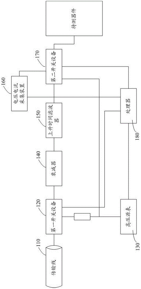
[0013] Such as figure 1 As shown, it is a schematic structural diagram of Embodiment 1 of the automatic transmission line pulse test system of the present invention, including: a transmission line 110, a first switching device 120, a high voltage source meter 130, an attenuator 140, a rise time filter 150, a voltage and current acquisition device 160, a second switching device 170, a processor 180;

[0014] The transmission line 110 is respectively connected to the attenuator 140 and the high voltage source meter 130 through the first switching device 120, the attenuator 140 is connected to the rise time filter 150, the rise time filter 150, the voltage and current acquisition device 160 and the high voltage source meter 130 are respectively The device under test is connect...


PUM


Abstract

An automatic transmission line pulse testing system is characterized in that a transmission line, a first switch device, a high voltage source meter, an attenuator, a rise time filter, a voltage and current collecting device, a second switch device and a processor are included; the transmission line is connected with the attenuator and the high voltage source meter through the first switch device, the attenuator is connected with the rise time filter, the rise time filter, the voltage and current collecting device and the high voltage source meter are connected with a device to be tested through the second switch device, and the processor is connected with the high voltage source meter, the voltage and current collecting device, the first switch device and the second switch device. The cost of the system is lowered, and the system is easy to implement and high in reliability.

Description

technical field [0001] The invention relates to the technical field of electrostatic discharge testing, in particular to an automatic transmission line pulse testing system. Background technique [0002] Integrated circuits are generally more susceptible to being damaged or destroyed by electrostatic discharge (ESD). The transmission line pulse (TLP) test is a main test method for verifying the anti-static discharge (ESD) design of integrated circuits. This technology tests the response characteristics of integrated circuits to high-power short pulses to evaluate their ESD protection capability. [0003] The existing TLP test system technical solution is to charge the transmission line by outputting a certain voltage through a high-voltage source. After charging, the transmission line discharges the device under test (DUT) through the attenuator and the rise time filter, and the voltage probe and current probe of the oscilloscope collect The voltage applied to the device u...

Claims


Application Information

Patent Timeline
IPC IPC(8): G01R31/00G01R31/28
Inventor 肖庆中罗宏伟师谦陈辉林晓玲
Owner FIFTH ELECTRONICS RES INST OF MINIST OF IND & INFORMATION TECH
Why Eureka
Try Eureka