
Optical digital sampling value relaying protection device-based sampling value display method and system

A relay protection device and display system technology, applied in general control systems, control/regulation systems, electrical program control, etc., can solve the problems of relay protection device panel confusion, hidden dangers of safe operation, frequent operations, etc., and achieve sampling values Display the effect of high discrimination, reliable calculation results and great application value

Active Publication Date: 2015-04-01
STATE GRID CORP OF CHINA +1
View PDF7 Cites 1 Cited by
  • Summary
  • Abstract
  • Description
  • Claims
  • Application Information

AI Technical Summary

Problems solved by technology

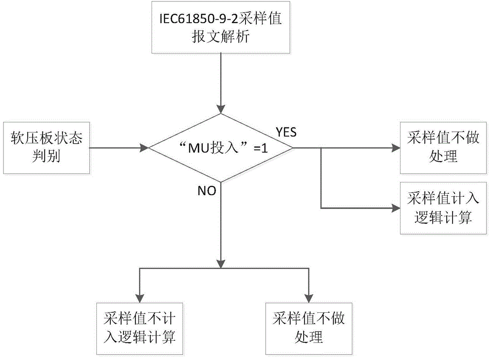
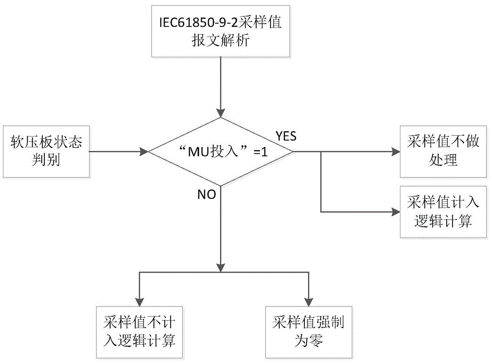
(Schematic as figure 2 ) In this method, the sampling value display on the panel before and after the "MU input" soft pressure plate exits the relay protection device has obvious changes, but the equipment operator cannot judge whether the sampling value is indeed zero at a certain interval or the channel setting caused by the "MU input" soft pressure plate exit. Zero, it is easy to cause frequent operations, wrong re-insertion after successful exit and other misoperations
[0007] Based on the above analysis, neither of the two display methods can enable equipment operators to simply and clearly judge the state of the MU input soft pressure plate, and the inconsistency will lead to confusion on the panel of the relay protection device, which will easily lead to the occurrence of false input and false exit of the MU soft pressure plate of the protection device , which brings hidden dangers to safe operation
Since the large-scale operation of smart substations, there have been many power outages in power grid enterprises due to the wrong switching of MU soft pressure plates, which have seriously affected the safe and stable operation of the power grid and the safe production of power consumers.

Method used


Image

  • Optical digital sampling value relaying protection device-based sampling value display method and system
  • Optical digital sampling value relaying protection device-based sampling value display method and system
  • Optical digital sampling value relaying protection device-based sampling value display method and system

Examples


Embodiment Construction

[0029] The present invention is described in detail below in conjunction with accompanying drawing:

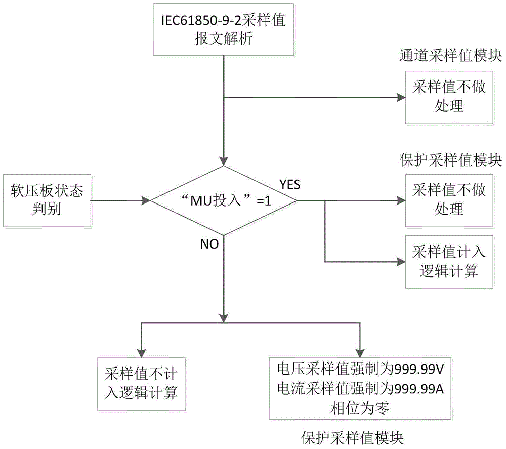
[0030] Such as image 3 , based on the sampling value display method of the optical digital sampling value relay protection device, the method distinguishes and displays the actual sampling value of the channel and the protection logic operation sampling value, and is applied to the relay protection device with optical digital input. This method is implemented with the following steps:

[0031] (1) The "Protection Sampling Value" and "Channel Sampling Value" modules are added to the software program of the relay protection device, and the "Protection Sampling Value" display interface and the "Channel Sampling Value" display interface are added to the device panel.

[0032] (2) The amplitude and phase of the optical digital input of the relay protection device conforming to the sampling value of IEC61850-9-2 are directly assigned to the "channel sampling value" module.

[003...


PUM


Abstract

The invention discloses an optical digital sampling value relaying protection device-based sampling value display method and system. The system includes a channel sampling module, a soft strap state judging module and a protection sampling value module; the channel sampling module is used for receiving the amplitude and phase of relaying protection device optical digital input which accords with an IEC61850-9-2 sampling value; the soft strap state judging module is used for judging whether the switching-in of an MU is realized, when the MU is switched in, the state of a soft strap is 1, and when the switching-in of the MU is not realized, the state of the soft strap is 0; the protection sampling value module is used for receiving the amplitude and phase of relaying protection device optical digital input which accords with the IEC61850-9-2 sampling value when the state of the soft strap is 1, and the sampling value enters protection logic calculation; MU-switching-in soft strap state judgment is completed through software programs without manual participation required; and therefore, calculation results are reliable, sampling value display has high discrimination degree, and whether the interval MU soft strap is switched in can be clearly distinguished. The optical digital sampling value relaying protection device-based sampling value display method and system have the advantages of convenient operation, safe and efficient work of maintenance personnel and great application value.

Description

technical field [0001] The invention relates to a sampling value display method and system based on an optical digital sampling value relay protection device. Background technique [0002] The voltage and current sampling in domestic smart substations is realized by the merging unit. The merging unit completes the analog quantity sampling and converts it into an optical signal in the IEC61850-9-2 sampling value transmission communication standard format, and transmits it to the relay protection device through optical fiber. According to the requirements for relay protection devices in Q / GDW441-2010 "Technical Specifications for Relay Protection of Smart Substations": (Relay protection device) The protection device connected to two or more MUs should be set according to the MU "MU input" soft pressure plate. The protection measurement and control device controls whether the current and voltage connected to each channel are included in the protection logic calculation through ...

Claims


Application Information

Patent Timeline
Patent Type & Authority Applications(China)
IPC IPC(8): G05B19/04
CPCG05B19/042
Inventor 孙运涛唐新建张婉婕黄秉青杨超赵斌超王军李玉敦王宏王昕张国辉
Owner STATE GRID CORP OF CHINA
Learn More