Eureka AIR delivers breakthrough ideas for toughest innovation challenges, trusted by R&D personnel around the world.

Configuration method and device of display units of joined screen system

A technology of a display unit and a configuration method, which is applied in the field of wall assembling systems, can solve the problems of being prone to errors, low efficiency, and inability to display unit positions corresponding to each other, and achieves the effect of improving configuration speed and work efficiency.

Inactive Publication Date: 2015-04-01
GUANGDONG VTRON TECH CO LTD
View PDF4 Cites 8 Cited by
  • Summary
  • Abstract
  • Description
  • Claims
  • Application Information

AI Technical Summary

Problems solved by technology

[0002] At present, the control of the splicing wall system is mostly realized through network control, and the problem of network control is that when the splicing wall system is first established on the PC-side control software to configure resources (that is, the physical location of the display unit and the distance between the virtual wall are established) mapping), can only receive the IP address information of the display unit, and cannot correspond to the location of the display unit
The significant disadvantage of this method is that it is inefficient and error-prone

Method used


Image

  • Configuration method and device of display units of joined screen system
  • Configuration method and device of display units of joined screen system
  • Configuration method and device of display units of joined screen system

Examples


Embodiment Construction

[0023] In order to make the purpose, technical solution and advantages of the present invention more clear, the present invention will be further described in detail below in conjunction with the accompanying drawings and embodiments. It should be understood that the specific embodiments described here are only used to explain the present invention, and do not limit the protection scope of the present invention.

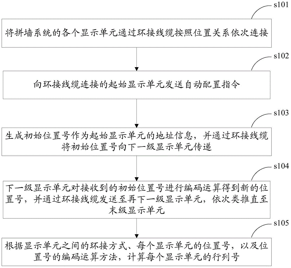
[0024] The configuration method of the display unit of the spelling wall system of the present invention, such as figure 1 shown, including steps:

[0025] Step s101 , connecting each display unit of the video wall system sequentially according to the positional relationship through the loop connection cable.

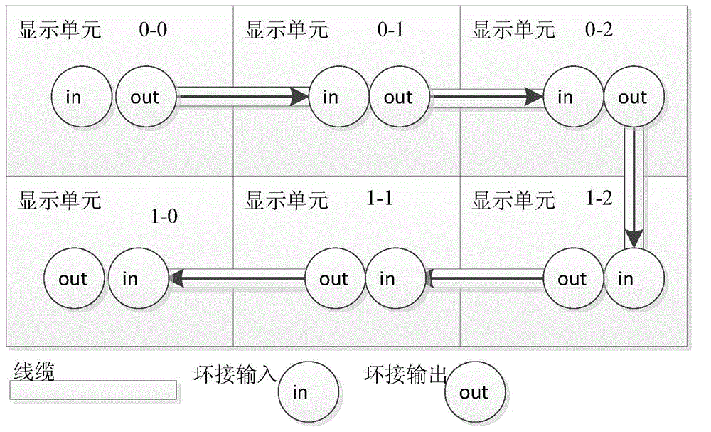
[0026] The existing coaxial cable can be used for the loop connection cable, so that the hardware cost does not need to be increased. The coaxial cable is used to realize the hardware synchronization among the display units, so that the images of the display...


PUM


Abstract

The invention discloses a configuration method and device of display units of a joined screen system. The display units are sequentially connected through looping-in cables, position information is transmitted through the looping-in cables, transcoding is carried out once every time when the position information is transmitted, and therefore the row number and line number of each display unit can be calculated according to a coding method, a looping-in mode and the position information of the display unit, and a corresponding relation can be established between the row numbers and line numbers and known IP addresses. Compared with a manual row number and line number determination mode, the method and device increase the configuration speed, improve the working efficiency of users and are especially suitable for the condition that the number of display units is large.

Description

technical field [0001] The present invention relates to the technical field of a video wall system, in particular to a method and a device for configuring a display unit of a video wall system. Background technique [0002] At present, the control of the splicing wall system is mostly realized through network control, and the problem of network control is that when the splicing wall system is first established on the PC-side control software to configure resources (that is, the physical location of the display unit and the distance between the virtual wall are established) mapping), can only receive the IP address information of the display unit, and cannot correspond to the location of the display unit. [0003] The traditional way to solve the above problem is to manually match the row and column number of each display unit with the IP address through human eye recognition. The obvious disadvantage of this method is that it is inefficient and error-prone. Contents of th...

Claims


Application Information

Patent Timeline
IPC IPC(8): G06F3/14
Inventor 马先
Owner GUANGDONG VTRON TECH CO LTD
Why Eureka
Eureka Blog
Learn More