Finite element model correction method based on positive substructure

A technology of model correction and substructure, applied in instrumentation, calculation, electrical and digital data processing, etc., can solve problems such as difficulty in cooperating with real-time health monitoring and status assessment, long calculation time, and many uncertain parameters.

Inactive Publication Date: 2015-04-01
HUAZHONG UNIV OF SCI & TECH
View PDF2 Cites 18 Cited by
  • Summary
  • Abstract
  • Description
  • Claims
  • Application Information

AI Technical Summary

Problems solved by technology

[0005] Large-scale fine-structured finite element models are usually composed of a large number of units and nodes. The finite element model and system matrix (stiffness matrix, mass matrix, damping matrix, etc.) need to occupy a large amount of memory space; the finite element model correction is an iterative process that requires Repeatedly extract the modal parameters and sensitivity matrix of the finite element model to achieve the goal of optimizing parameters; repeated finite element model analysis (for example: extracting eigensolutions, solving sensitivity matrix) requires high hardware equipment and long computing time; There are a large number of material, geometric properties and boundary condition assumptions in the finite element model of large structures, and the structural parameters that need to be corrected are bound to increase. A large number of corrected parameters will make the optimization process prone to ill-conditioned or slow convergence problems, and the optimization results are not good.
In addition, large-scale structural finite element models usually consist of tens of thousands of units and nodes, with many uncertain parameters, resulting in low efficiency and poor accuracy in the model correction process, and it is difficult to cooperate with real-time health monitoring and state assessment, which limits the use of finite element model correction technology. Widely used in civil engineering structures

Method used


Image

  • Finite element model correction method based on positive substructure
  • Finite element model correction method based on positive substructure
  • Finite element model correction method based on positive substructure

Examples


Embodiment Construction

[0062] In order to make the object, technical solution and advantages of the present invention clearer, the present invention will be further described in detail below in conjunction with the accompanying drawings and embodiments. It should be understood that the specific embodiments described here are only used to explain the present invention, not to limit the present invention. In addition, the technical features involved in the various embodiments of the present invention described below can be combined with each other as long as they do not constitute a conflict with each other.

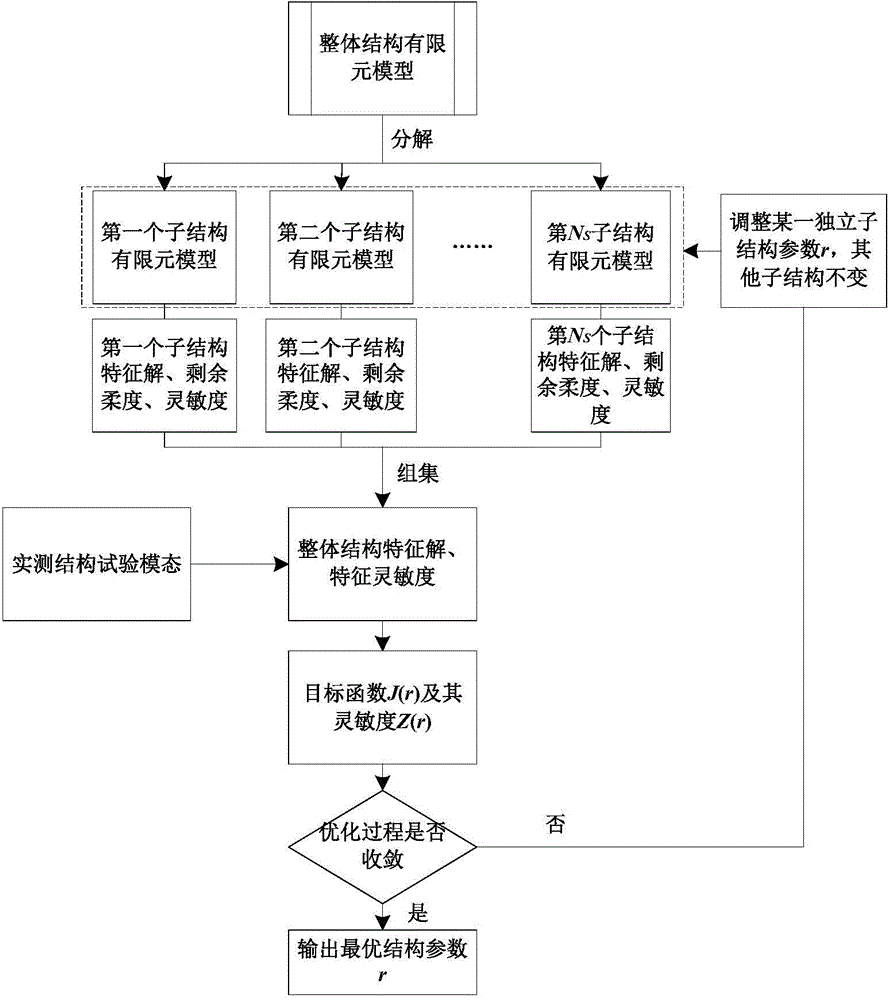
[0063] Divide the finite element model of the overall structure into multiple independent substructure finite element models, and solve the eigensolution and sensitivity matrix of the overall structure by solving one or several changed independent substructure eigensolutions and their sensitivity matrices, and use them in the finite element model Correction and damage identification. The so-cal...


PUM


Abstract

The invention discloses a finite element model correction method based on a positive substructure. The finite element model correction method includes the steps: firstly, dividing an integral structure finite element model into independent substructure models; building an integral structure characteristic equation according to the substructure models to obtain an integral structure characteristic solution; building an integral structure characteristic sensitivity equation according to the integral structure characteristic equation to obtain an integral structure characteristic solution sensitivity matrix; building a target function according to residual errors of the integral structure characteristic solution and a measured integral structure test mode; adjusting structural parameters of the substructure and minimizing the target function to obtain optimal structural parameters; adjusting structural parameters of the finite element model and correcting the finite element model; recognizing structural damage according to change of result parameters of the finite element model. When a structure is locally damaged and a local area needs to be corrected, large structure finite element model correction efficiency and precision are effectively improved only by iteratively analyzing the local substructure models without repeatedly analyzing the integral structure model.

Description

technical field [0001] The invention belongs to the technical field of civil engineering large-scale structure detection, and more specifically relates to a finite element model correction method based on a forward substructure. Background technique [0002] Civil engineering structures are an important part of national infrastructure, and the safety of structures is directly related to people's lives, property safety and social stability. With the rapid development of the economy, a large number of high-rise buildings, large space structures and long-span bridges have been built in our country. In order to ensure the safe construction and normal long-term operation of these structures, it is necessary to conduct short-term and long-term monitoring and evaluation of the safety, integrity and durability of civil engineering structures. Therefore, an accurate finite element model is an important basis for structural dynamic analysis and health assessment, and structural healt...

Claims


Application Information

Patent Timeline
Patent Type & Authority Applications(China)
IPC IPC(8): G06F17/50G06F19/00
Inventor 朱宏平翁顺夏勇毛羚
Owner HUAZHONG UNIV OF SCI & TECH
Why Eureka
Try Eureka