
Support for lithographic printing plate and manufacturing method therefor, as well as original lithographic printing plate

一种平版印刷版、支撑体的技术,应用在平版印刷版用支撑体领域,能够解决暗调部堵塞、水裕度变窄、保水性低等问题,达到耐划伤性优异、优异耐划伤性、耐刷性优异的效果

Active Publication Date: 2015-04-01
FUJIFILM CORP
View PDF40 Cites 10 Cited by
  • Summary
  • Abstract
  • Description
  • Claims
  • Application Information

AI Technical Summary

Problems solved by technology

In addition, if the water retention of the support is too low, when there is not much fountain solution during printing, the shaded part will be clogged
Thus, the so-called water allowance is narrowed

Method used


Image

  • Support for lithographic printing plate and manufacturing method therefor, as well as original lithographic printing plate
  • Support for lithographic printing plate and manufacturing method therefor, as well as original lithographic printing plate
  • Support for lithographic printing plate and manufacturing method therefor, as well as original lithographic printing plate

Examples


Embodiment A

[0334]

[0335] The following processes (a) to (n) were performed on an aluminum alloy plate having a composition shown in Table A having a thickness of 0.3 mm to manufacture a support for a lithographic printing plate. In addition, water washing treatment is performed between all the treatment steps, and liquid removal is performed with nip rolls after the water washing treatment.

[0336] In addition, Table A discloses the compositions of the aluminum alloy plates used in Examples 1 to 30 and Comparative Examples 1 to 22 described later, and the numerical values ​​in each component column represent mass %, and the parts other than that are A1.

[0337] [Table 1]

[0338] Table A

[0339]

[0340] (a) Mechanical roughening treatment (brushing and grinding method)

[0341] use as Image 6 As shown in the device, the suspension of pumice (specific gravity is 1.1g / cm 3 ) to make an abrasive slurry and supply it to the surface of the aluminum plate, while mechanically ro...

Embodiment B

[0467]

[0468] For each of the supports for lithographic printing plates produced above (Examples 1-3, 5, 16, Comparative Examples 1-3, 15), a solution containing 4 g / l of polyvinylphosphonic acid was used for 10 seconds at 40 Post-treatment was performed at 20° C., rinsed with desalted water for 2 seconds at 20° C., and then dried.

[0469] Next, the following image recording layer coating liquid was bar-coated on the above-mentioned substrate, and then dried in an oven at 50° C. for 60 seconds to obtain a dry coating weight of 0.91 g / m 2 image recording layer.

[0470]

[0471]

[0472] The structure of the infrared absorber (2) is shown below.

[0473] [Chemical formula 5]

[0474]

[0475] The above-mentioned various evaluations were performed on the obtained lithographic printing plate precursor. The results are collectively shown in Table 4. In addition, Examples and Comparative Examples implemented using the supports for lithographic printing plates produ...


PUM

PropertyMeasurementUnit
diameteraaaaaaaaaa
widthaaaaaaaaaa
diameteraaaaaaaaaa

Abstract

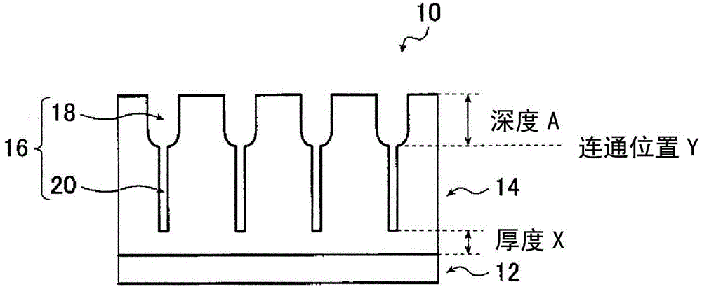
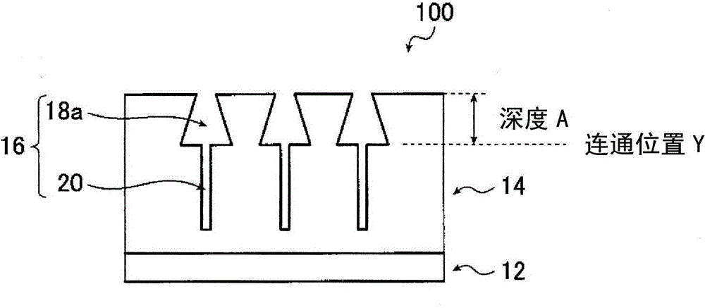
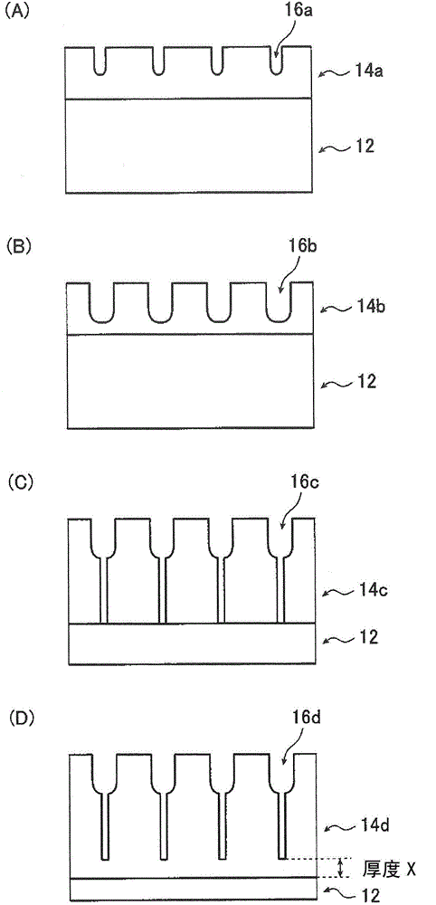
The purpose of the present invention is to provide a support for a lithographic printing plate. The support has excellent scratch resistance and with the support, an original lithographic printing plate that has excellent printing durability when used as a lithographic printing plate and exhibits excellent on-machine developability can be obtained. For this support for a lithographic printing plate, which is provided with an aluminum plate and an anodized aluminum film thereon and which has micropores in the anodized film that extend in the depth direction from the surface that is on the opposite side from the aluminum plate: the micropores are configured from a large diameter hole section that extends from the surface of the anodized film to a mean depth of 75 - 120 nm (depth (A)) and a small diameter hole section that connects with the bottom of the large diameter hole section and extends from the connection position to a mean depth of 900-2000 nm; the mean diameter at the anodized film surface of the large diameter hole section is 10 nm to less than 30 nm, and the mean diameter and the depth (A) satisfy the relationship (depth (A) / mean diameter) = greater than 4.0 to 12.0; and the mean diameter at the connection position of the small diameter pore section is greater than 0 and less than 10 nm.

Description

technical field [0001] The present invention relates to a support for lithographic printing plates, a method for producing the same, and a precursor for lithographic printing plates. Background technique [0002] The lithographic printing method is a printing method in which water and oil are substantially immiscible with each other, and a region (hereinafter referred to as "non-image area") that accepts water and repels oily ink is formed on the printing plate of the lithographic printing plate used therein. ".) and a region that repels water and accepts oily ink (hereinafter, this region is referred to as an "image portion."). [0003] Aluminum supports for lithographic printing plates (hereinafter, simply referred to as "supports for lithographic printing plates") used in lithographic printing plates are used in such a way that the surface bears the non-image area, so it is required to be excellent in hydrophilicity and water retention, Furthermore, various performances ...

Claims


Application Information

Patent Timeline
Patent Type & Authority Applications(China)
IPC IPC(8): B41N3/03B41N1/14G03F7/00G03F7/09
CPCB41N3/034C25F3/04C25D11/08C25D11/12C25D11/16C25D11/24C25D11/005B41N1/083B41N1/14
Inventor 田川义治黑川真也松浦睦宫川侑也泽田宏和西野温夫
Owner FUJIFILM CORP
Learn More