
Battery tab bending mechanism

A technology of bending mechanism and battery tabs, applied in battery pack parts, circuits, electrical components, etc., can solve the problems of manual battery removal speed limit, unstable manual operation, increased labor cost and management cost, etc. Achieve the effect of reducing defect rate, reducing production cost, improving work efficiency and accuracy

Inactive Publication Date: 2015-04-08
SUZHOU SUNMICRO AUTOMATION TECH CO LTD
View PDF10 Cites 2 Cited by
  • Summary
  • Abstract
  • Description
  • Claims
  • Application Information

AI Technical Summary

Problems solved by technology

[0004] In the process of battery tab processing, it is necessary to bend the positive and negative tabs drawn from the battery core so that the bent tabs are flush with the upper surface of the battery core. Currently, the tab bending process is generally It depends on manual work, which not only increases labor costs and management costs, but also affects the accuracy of battery tab bending due to the instability of manual operations
In addition, with the expansion of production scale and the increase of production line speed, there is a great limitation in the speed of manual battery removal, which cannot meet the speed requirements of modern large-scale industrial production lines.

Method used


Image

  • Battery tab bending mechanism
  • Battery tab bending mechanism
  • Battery tab bending mechanism

Examples


Embodiment Construction

[0025] The technical solutions of the embodiments of the present invention will be clearly and completely described below in conjunction with the accompanying drawings of the present invention.

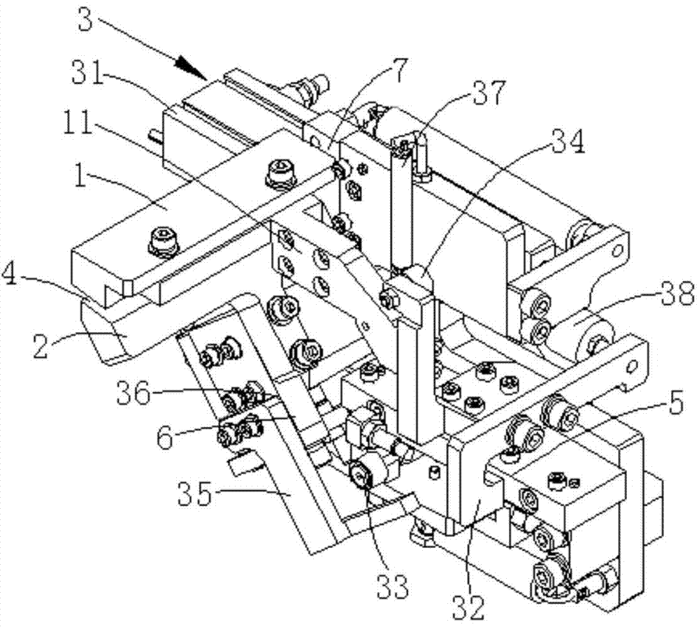
[0026] A battery tab bending mechanism disclosed in the present invention is used for automatically bending the battery tab. like figure 1 As shown, the battery lug bending mechanism of Embodiment 1 of the present invention includes an upper bending head 1, a lower bending head 2, and a bending head driving mechanism 3, and the upper bending head 1 and the lower bending head 2 are arranged opposite to each other up and down. And a bending gap 4 is formed between the two, and the battery tab is located in the bending gap 4 during bending. The lower bending head 2 rises to be flush with the upper surface of the battery cell under the drive of the bending head driving mechanism 3, and the upper bending head 1 is pressed down to meet the lower bending head 2 under the driving of the bend...


PUM


Abstract

The invention discloses a battery tab bending mechanism. The mechanism comprises an upper bending head, a lower bending head and a bending head driving mechanism, wherein the upper bending head and the lower bending head vertically face each other; a bending gap is formed between the upper bending head and the lower bending head; the bending head driving mechanism comprises a first cylinder, a moving plate, a first cam bearing, a second cam bearing and a cam bearing slide block; the moving plate is connected with the first cylinder; the first cam bearing and the second cam bearing are both connected with the moving plate; the first cam bearing is connected with the lower bending head through the cam bearing slide block; the second cam bearing is connected with the upper bending head; the motor drives the moving plate to move, and synchronously drives the first cam bearing and the second cam bearing to move; the first cam bearing drives the lower bending head to ascend through the cam bearing slide block; the second cam bearing drives the upper bending head to descend. The mechanism can realize automatic bending of battery tabs, improves the working efficiency and the precision of the tab bending, reduces the production cost, and can achieve the speed requirements of modern great industry production lines.

Description

technical field [0001] The invention relates to the field of battery manufacturing and assembling equipment, in particular to a battery tab bending mechanism for automatically bending battery core tabs. Background technique [0002] At present, the rapid development of electronic technology, its cost performance is getting higher and higher, resulting in the extensive attention of the performance of the battery. In recent years, with the widespread popularization and development of communication technology, higher requirements have been put forward for battery capacity, safety, battery tab spacing and battery packaging. [0003] Tabs are a raw material for the production of lithium-ion polymer batteries, such as mobile phone batteries, Bluetooth batteries, and notebook batteries used in daily life. The battery is divided into positive and negative poles, and the tab is the metal conductor that leads the positive and negative poles out of the battery cell. In the battery pr...

Claims


Application Information

Patent Timeline
IPC IPC(8): B21D5/00H01M2/26H01M50/531
CPCB21D5/00H01M50/531Y02E60/10
Inventor 吴杨飞李纲龙军
Owner SUZHOU SUNMICRO AUTOMATION TECH CO LTD
Learn More